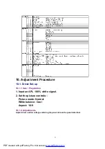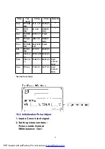
Adjust the indicated test point for the specified wave form.
Test point
Volume
Level
T1
TPSC1 (SC)
---
15 ± 10
Sec
T2
TPSS1 (SS)
VR6557 (SC)
184 + 5
/ - 10
Sec
10.3. P.C.B. (Printed Circuit Board) exchange
10.3.1. Caution
1. To remove P.C.B. , wait 1 minute after power was off for discharge
from electrolysis capacitors.
10.3.2. Quick adjustment after P.C.B. exchange
P.C.B.
Name
Test Point
Voltage
Volume
Remarks
P Board
Vsus
TPVSUS (SS)
Vsus ± 1V
R628 (P)
*
Vda
TPVDA (SS)
67V ± 1V
R665 (P)
PFC
C446 (+) (-) (P)
395V ± 0.5V
R443 (P)
Vlow
C557 (+) (-) (P)
73V ± 0.1V
R661 (P)
load current :
0.4A
Csus
TPVSUS (SS)
174V ± 0.5V
R671 (P)
load current :
0.6A
SC Board
Vad
TPVAD (SC)
-90V ± 1V
VR6477 (SC)
SS Board
Ve
TPVE (SS)
Ve ± 2V
VR6074 (SS)
*
D, DG Board
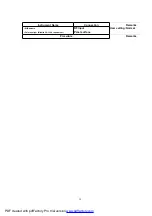
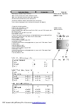
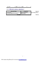
White blance, Pedestal and Sub brightness for NTSC, PAL, HD, PC and 625i signals
*See the Panel label.
33
PDF created with pdfFactory Pro trial version
Summary of Contents for TH-42PE55E
Page 22: ...22 PDF created with pdfFactory Pro trial version www pdffactory com ...
Page 29: ...9 3 Option Description 29 PDF created with pdfFactory Pro trial version www pdffactory com ...
Page 30: ...30 PDF created with pdfFactory Pro trial version www pdffactory com ...
Page 49: ...49 PDF created with pdfFactory Pro trial version www pdffactory com ...
Page 51: ...51 PDF created with pdfFactory Pro trial version www pdffactory com ...
Page 129: ...14 Block and Schematic Diagram 14 1 Schematic Diagram Notes 67 ...
Page 130: ...14 Block and Schematic Diagram 14 1 Schematic Diagram Notes 67 ...


