Adjust driver section voltages referring the panel data on the panel data label.
Name
Test
Point
Voltage
Volume
Remarks
Vsus
TPVSUS
(SS)
170V ± 2V
VR641 (P)
Ve
TPVE
(SS)
150V ± 1V
R6770
(SS)
Vset
TPVSET
(SC)
220V ± 5V
---
Vad
TPVAD
(SC)
-90V ± 1V
R6477
(SC)
Vscn
TPVSCN
(SC)
Vad*+118V
± 2V
---
Vda
TPVDA
(SS)
67V ± 1V
VR665 (P)
*See the Panel label.
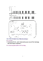
10.2. Initialization Pulse Adjust
1. Input a Cross hatch signal.
2. Set the picture controls: -
Picture mode: Normal
White balance: Cool
Adjust the indicated test point for the specified wave form.
Test point
Volume
Level
T1
TPSC1 (SC)
---
20 ± 15 Sec
T2
TPSS1 (SS)
R6557 (SC)
170 ± 10 Sec
23
Summary of Contents for TH-42PX20U/P Operating
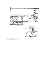
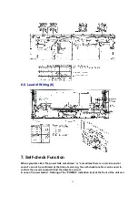
Page 9: ...6 2 Lead of Wiring 2 9 ...
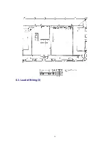
Page 10: ...6 3 Lead of Wiring 3 10 ...
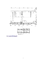
Page 11: ...6 4 Lead of Wiring 4 11 ...
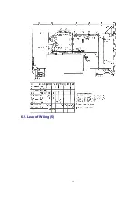
Page 12: ...6 5 Lead of Wiring 5 12 ...
Page 34: ...15 2 Parts Location 2 34 ...
Page 35: ...15 3 Parts Location 3 35 ...
Page 36: ...36 ...
Page 37: ...15 4 Parts Location 4 15 5 Parts Location 5 37 ...
Page 38: ...38 ...
Page 42: ...17 2 Electrical Replacement Parts List 42 ...
Page 54: ...D12 K1KA07A00189 7P CONNECTOR 1 54 ...
Page 348: ...1 Applicable signals 4 TH 42PX20U P ...
Page 353: ...6 Location of Lead Wiring 6 1 Lead of Wiring 1 9 TH 42PX20U P ...
Page 354: ...6 2 Lead of Wiring 2 10 TH 42PX20U P ...
Page 355: ...6 3 Lead of Wiring 3 11 TH 42PX20U P ...
Page 356: ...6 4 Lead of Wiring 4 12 TH 42PX20U P ...
Page 357: ...6 5 Lead of Wiring 5 13 TH 42PX20U P ...
Page 358: ...6 6 Lead of Wiring 6 14 TH 42PX20U P ...
Page 367: ...9 4 IIC mode structure following items value is sample data 23 TH 42PX20U P ...
Page 376: ...32 TH 42PX20U P ...

