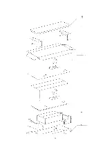
13.18. G-Board
13.19. K and S-Board
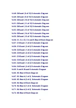
14. Block and Schematic Diagrams
14.1. Schematic Diagram Notes
14.2. Main Block Diagram
14.3. PF-Board Block Diagram
14.4. PF-Board Schematic Diagram
14.5. P-Board Block Diagram
14.6. P-Board (1 of 6) Schematic Diagram
14.7. P-Board (2 of 6) Schematic Diagram
14.8. P-Board (3 of 6) Schematic Diagram
14.9. P-Board (4 of 6) Schematic Diagram
14.10. P-Board (5 of 6) Schematic Diagram
14.11. P-Board (6 of 6) Schematic Diagram
14.12. PA and G-Board Block Diagram
14.13. PA-Board (1 of 3) Schematic Diagram
14.14. PA-Board (2 of 3) Schematic Diagram
14.15. PA-Board (3 of 3) Schematic Diagram
14.16. G-Board Schematic Diagram
14.17. TA, TB and H-Board Block Diagram
14.18. TA and TB-Board Schematic Diagram
14.19. H-Board (1 of 2) Schematic Diagram
14.20. H-Board (2 of 2) Schematic Diagram
14.21. DV-Board Block Diagram
14.22. DV-Board (1 of 3) Schematic Diagram
30
Summary of Contents for TH-42PX20U/P Operating
Page 9: ...6 2 Lead of Wiring 2 9 ...
Page 10: ...6 3 Lead of Wiring 3 10 ...
Page 11: ...6 4 Lead of Wiring 4 11 ...
Page 12: ...6 5 Lead of Wiring 5 12 ...
Page 34: ...15 2 Parts Location 2 34 ...
Page 35: ...15 3 Parts Location 3 35 ...
Page 36: ...36 ...
Page 37: ...15 4 Parts Location 4 15 5 Parts Location 5 37 ...
Page 38: ...38 ...
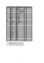
Page 42: ...17 2 Electrical Replacement Parts List 42 ...
Page 54: ...D12 K1KA07A00189 7P CONNECTOR 1 54 ...
Page 348: ...1 Applicable signals 4 TH 42PX20U P ...
Page 353: ...6 Location of Lead Wiring 6 1 Lead of Wiring 1 9 TH 42PX20U P ...
Page 354: ...6 2 Lead of Wiring 2 10 TH 42PX20U P ...
Page 355: ...6 3 Lead of Wiring 3 11 TH 42PX20U P ...
Page 356: ...6 4 Lead of Wiring 4 12 TH 42PX20U P ...
Page 357: ...6 5 Lead of Wiring 5 13 TH 42PX20U P ...
Page 358: ...6 6 Lead of Wiring 6 14 TH 42PX20U P ...
Page 367: ...9 4 IIC mode structure following items value is sample data 23 TH 42PX20U P ...
Page 376: ...32 TH 42PX20U P ...

