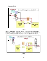
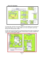
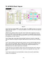
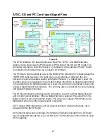
Power On Operation
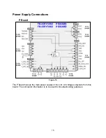
Figure 11
12
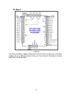
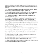
The momentary connection of the power switch to ground supplies a low to the base of
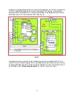
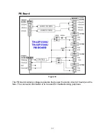
he R/C receiver receives the power on command of the remote control and outputs the
Q4001 (DG board) to turn it on. When Q4001 is on, a low is provided to pin 86 (Key
scan 3) of the microprocessor IC4005.
T
IR data to the amplifiers Q4006 and Q4007 of the DG board. The data is amplified and
output to pin 102 of the MPU, IC4005.
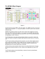
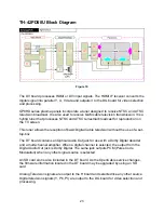
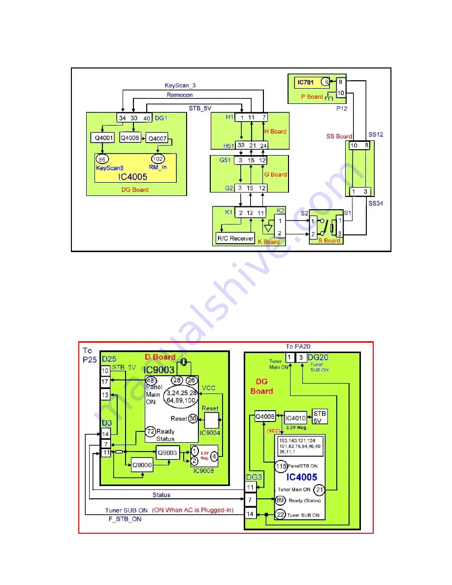
Figure 12
Summary of Contents for TH-42PX50U
Page 40: ...SC board Waveform Figure 30 SU And SD Board Shift Registers Figure 31 35 ...
Page 43: ...SS Board Schematic Figure 33 SS Board Waveform Figure 34 38 ...
Page 66: ...Adjustment Volume Locations Figure 53 61 ...
Page 67: ...Test Point Locations Figure 54 62 ...
Page 71: ...Scan and Sustain Drive Waveform Figure 55 Scan and Sustain Drive Check points Figure 56 66 ...


