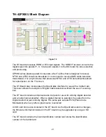
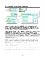
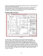

It also processes the JPEG data of the SD and PC cards used for viewing pictures.
Photo-viewer data from the G and GS boards are input to the DT board and converted
to analog luminance and chrominance signals. Analog Television and Photo-viewer
signals are output to the H board and selected like any other source. Digital television
signals (Y, Pb, Pr) are output to the DG board for video selection and processing.
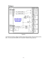
The GS board contains the SD card slot that is used for Photo-viewing. The digital
output signal passes through the H board and enters the DT board for processing.
The GK is the operation board of the unit. The key scan pulses are routed to the DG
board MPU via the G and H boards.
The G board contains one of the video inputs and the PC card slot, which is used for
viewing photos. The digital output signal of the PC card passes through the H board and
enters the DT board for selection and processing. The analog video input signal is
provided to the H board for selection among many other video inputs.
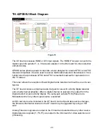
The K board contains the optical sensor used for CATS (Contrast Automatic Tracking
System). It also contains the Remote IR sensor and the power LED.
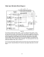
The unit also contains two other video inputs, two component inputs, and a PC input
(depending upon the model) that are directly connected to the main switch of the H
board.
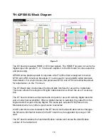
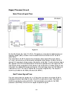
The H board selects and outputs, to the DG board, the main video and sub video
signals for display on the screen.
The DG board is responsible for the complete video processing within the unit. All
analog inputs to the DG board are immediately converted to digital. All signal
processing in the DG board is performed digitally. Signals from a digital TV or HDMI
source are provided to the DG board in digital form. The board performs PIP (Picture in
Picture) and
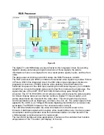
picture control operations such as brightness, contrast, color, tint, etc. The
board also performs pixel conversion to change the resolution of the picture to the
resolution of the screen. The output signal of the board passes through an LVDS (Low
Voltage Differential Signaling) transmitter for conversion into serial data. The PEAKS
firmware of the unit also resides in this board.
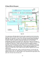
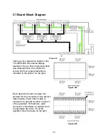
The D board is responsible for displaying the picture on the screen. It provides the scan,
sustain and data drive signals. The scan pulses are output to the SC board. The sustain
pulses are output to the SS board. The data drive signals are output to the C1, C2, C3
and C4 boards. The C1 board drives the upper right portion of the panel; the C2 board
drives the upper left portion. The C3 and C4 boards drive the lower right and left
portions of the panel respectively.
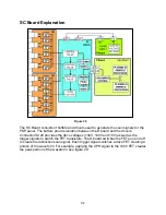
The SC board is responsible for the generation of the scan pulses. Scan pulses are
used for initialization and selection of the pixels.
19
Summary of Contents for TH-42PX50U
Page 40: ...SC board Waveform Figure 30 SU And SD Board Shift Registers Figure 31 35 ...
Page 43: ...SS Board Schematic Figure 33 SS Board Waveform Figure 34 38 ...
Page 66: ...Adjustment Volume Locations Figure 53 61 ...
Page 67: ...Test Point Locations Figure 54 62 ...
Page 71: ...Scan and Sustain Drive Waveform Figure 55 Scan and Sustain Drive Check points Figure 56 66 ...


