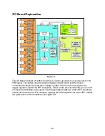
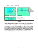
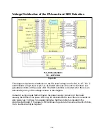
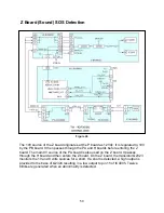
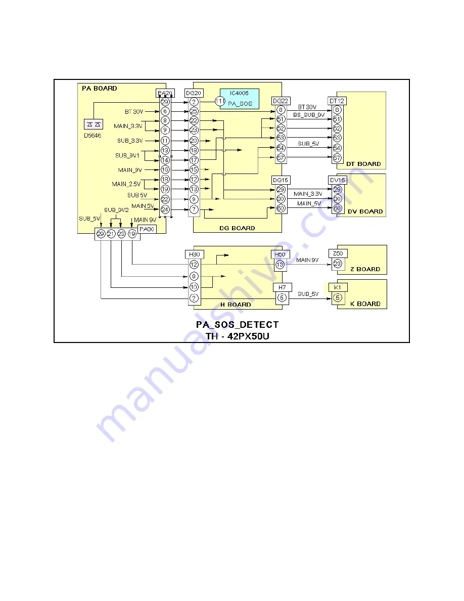
Voltage Distribution of the PA board and SOS Detection
Figure 44
This diagram depicts the distribution of the PA board voltages to the DG, H, DT, DV, Z,
and K boards. A high input at pin 111 of IC4005 will cause the unit to shut down and
generate ten blinks of the power LED. This SOS condition is created when there is an
abnormality of any of the voltages shown in the diagram.
Instead of using a peak hold voltmeter, the power supply connector of the board
causing the blinks of the power LED may be disconnected to see if the unit remains on
after power up. If it does, this usually indicates that the problem is located in the
disconnected board. If the power LED continues to generate the same amount of blinks,
more troubleshooting is required.
48
Summary of Contents for TH-42PX50U
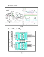
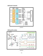
Page 40: ...SC board Waveform Figure 30 SU And SD Board Shift Registers Figure 31 35 ...
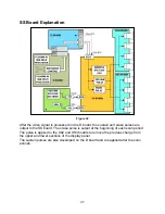
Page 43: ...SS Board Schematic Figure 33 SS Board Waveform Figure 34 38 ...
Page 66: ...Adjustment Volume Locations Figure 53 61 ...
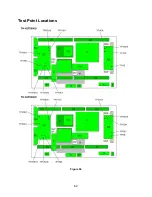
Page 67: ...Test Point Locations Figure 54 62 ...
Page 71: ...Scan and Sustain Drive Waveform Figure 55 Scan and Sustain Drive Check points Figure 56 66 ...


