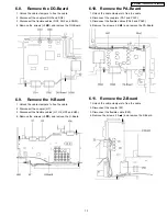

6.37. Remove the K-Board
22
6.38. Remove the S-Board
22
6.39. Remove the Plasma panel section from the Front frame
(glass)
22
6.40. Replace the plasma panel (finished).
23
7
Location of Lead Wiring
24
7.1.
Lead of Wiring (1)
24
7.2.
Lead of Wiring (2)
25
7.3.
Lead of Wiring (3)
26
7.4.
Lead of Wiring (4)
27
7.5.
Lead of Wiring (5)
28
7.6.
Lead of Wiring (6)
29
7.7.
Lead of Wiring (7)
30
7.8.
Lead of Wiring (8)
31
7.9.
Lead of Wiring (9)
32
7.10. Lead of Wiring (10)
33
8
Self-check Function
34
8.1.
How to access
34
8.2.
Power LED Blinking timing chart
35
8.3.
No Power
36
8.4.
No Picture
37
8.5.
Local screen failure
38
9
Serviceman Mode
39
9.1.
How to enter into Serviceman Mode
39
9.2.
Cancellation
39
9.3.
Contents of adjustment mode
39
9.4.
Option
40
10 Adjustment Procedure
41
10.1. Driver Set-up
41
10.2. Initialization Pulse Adjust
42
10.3. P.C.B. (Printed Circuit Board) exchange
43
10.4. Adjustment Volume Location
44
10.5. Test Point Location
45
11 Hotel mode
46
12 Conductor View
47
12.1. P-Board (37inch)
47
12.2. P-Board (42inch)
50
12.3. P-Board (50inch)
53
12.4. PA-Board
56
12.5. PB-Board
57
12.6. H-Board
58
12.7. DT-Board
60
12.8. DV-Board
62
12.9. DG-Board
63
12.10. Z-Board
65
12.11. D-Board (37, 42inch)
66
12.12. D-Board (50inch)
69
12.13. C1-Board (37inch)
72
12.14. C2-Board (37inch)
73
12.15. C3-Board (37inch)
74
12.16. C4-Board (37inch)
75
12.17. C1-Board (42inch)
76
12.18. C2-Board (42inch)
77
12.19. C3-Board (42inch)
78
12.20. C4-Board (42inch)
79
12.21. C1-Board (50inch)
80
12.22. C2-Board (50inch)
81
12.23. C3-Board (50inch)
82
12.24. C4-Board (50inch)
83
12.25. C5-Board (50inch)
84
12.26. C6-Board (50inch)
85
12.27. SC-Board (37inch)
86
12.28. SC-Board (42inch)
89
12.29. SC-Board (50inch)
92
12.30. SU-Board (37inch)
95
12.31. SU-Board (42inch)
96
12.32. SU-Board (50inch)
97
12.33. SD-Board (37inch)
98
12.34. SD-Board (42inch)
99
12.35. SD-Board (50inch)
100
12.36. SS-Board (37inch)
101
12.37. SS, SS2 and SS3-Board (42inch)
103
12.38. SS, SS2 and SS3-Board (50inch)
105
12.39. K and S-Board
107
13 Block and Schematic Diagram
109
13.1. Schematic Diagram Notes
109
13.2. Main Block Diagram (37inch)
110
13.3. Main Block Diagram (42inch)
111
13.4. Main Block Diagram (50inch)
112
13.5. P-Board Block Diagram (37inch)
113
13.6. P-Board (1 of 6) Schematic Diagram (37inch)
114
13.7. P-Board (2 of 6) Schematic Diagram (37inch)
115
13.8. P-Board (3 of 6) Schematic Diagram (37inch)
116
13.9. P-Board (4 of 6) Schematic Diagram (37inch)
117
13.10. P-Board (5 of 6) Schematic Diagram (37inch)
118
13.11. P-Board (6 of 6) Schematic Diagram (37inch)
119
13.12. P-Board Block Diagram (42inch)
120
13.13. P-Board (1 of 2) Schematic Diagram (42inch)
121
13.14. P-Board (2 of 2) Schematic Diagram (42inch)
122
13.15. P-Board Block Diagram (50inch)
123
13.16. P-Board (1 of 2) Schematic Diagram (50inch)
124
13.17. P-Board (2 of 2) Schematic Diagram (50inch)
125
13.18. PA and PB Board Block Diagram
126
13.19. PA-Board Schematic Diagram
127
13.20. PB-Board Schematic Diagram
128
13.21. H, K, S and Z-Board Block Diagram
129
13.22. H-Board (1 of 3) Schematic Diagram
130
13.23. H-Board (2 of 3) Schematic Diagram
131
13.24. H-Board (3 of 3) Schematic Diagram
132
13.25. Z-Board Schematic Diagram
133
13.26. K and S-Board Schematic Diagram
134
13.27. DV-Board Block Diagram
135
13.28. DV-Board Schematic Diagram
136
13.29. DT-Board Block Diagram
137
13.30. DT-Board (1 of 5) Schematic Diagram
138
13.31. DT-Board (2 of 5) Schematic Diagram
139
13.32. DT-Board (3 of 5) Schematic Diagram
140
13.33. DT-Board (4 of 5) Schematic Diagram
141
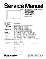
3
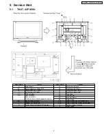
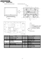
TH-37PX50U / TH-42PX50U / TH-50PX50U
Summary of Contents for TH-42PX50U
Page 24: ...7 Location of Lead Wiring 7 1 Lead of Wiring 1 TH 37PX50U 24 TH 37PX50U TH 42PX50U TH 50PX50U ...
Page 25: ...7 2 Lead of Wiring 2 TH 37PX50U 25 TH 37PX50U TH 42PX50U TH 50PX50U ...
Page 26: ...7 3 Lead of Wiring 3 TH 42PX50U 26 TH 37PX50U TH 42PX50U TH 50PX50U ...
Page 27: ...7 4 Lead of Wiring 4 TH 42PX50U 27 TH 37PX50U TH 42PX50U TH 50PX50U ...
Page 28: ...7 5 Lead of Wiring 5 TH 50PX50U 28 TH 37PX50U TH 42PX50U TH 50PX50U ...
Page 29: ...7 6 Lead of Wiring 6 TH 50PX50U 29 TH 37PX50U TH 42PX50U TH 50PX50U ...
Page 30: ...7 7 Lead of Wiring 7 30 TH 37PX50U TH 42PX50U TH 50PX50U ...
Page 31: ...7 8 Lead of Wiring 8 TH 37PX50U 31 TH 37PX50U TH 42PX50U TH 50PX50U ...
Page 32: ...7 9 Lead of Wiring 9 TH 42PX50U 32 TH 37PX50U TH 42PX50U TH 50PX50U ...
Page 33: ...7 10 Lead of Wiring 10 TH 50PX50U 33 TH 37PX50U TH 42PX50U TH 50PX50U ...
Page 37: ...8 4 No Picture 37 TH 37PX50U TH 42PX50U TH 50PX50U ...
Page 40: ...9 4 Option 40 TH 37PX50U TH 42PX50U TH 50PX50U ...
Page 44: ...10 4 Adjustment Volume Location 44 TH 37PX50U TH 42PX50U TH 50PX50U ...
Page 45: ...10 5 Test Point Location 45 TH 37PX50U TH 42PX50U TH 50PX50U ...
Page 108: ...TH 37PX50U TH 42PX50U TH 50PX50U 108 ...
Page 228: ...14 2 Pcaking Exploded Views 1 228 TH 37PX50U TH 42PX50U TH 50PX50U ...
Page 229: ...14 3 Pcaking Exploded Views 2 229 TH 37PX50U TH 42PX50U TH 50PX50U ...
Page 230: ...14 4 Pcaking Exploded Views 3 230 TH 37PX50U TH 42PX50U TH 50PX50U ...


