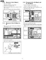

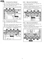


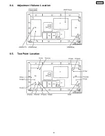
6.10. Removal of the D-Board
1. Remove the Slot Block.
(Reference to Removal of the Slot Block)
2. Disconnect the couplers(D5, D20)
3. Remove the Flexible Cable from the couplers (D3, D31,
D32, D33, D34).
4. Remove the 4 screws and then remove the D-Board.
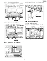
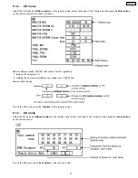
6.11. Removal of the H3-Board (L,
R)
1. Remove
1 screw
each
and then remove the Speaker
Terminal Block (L, R).
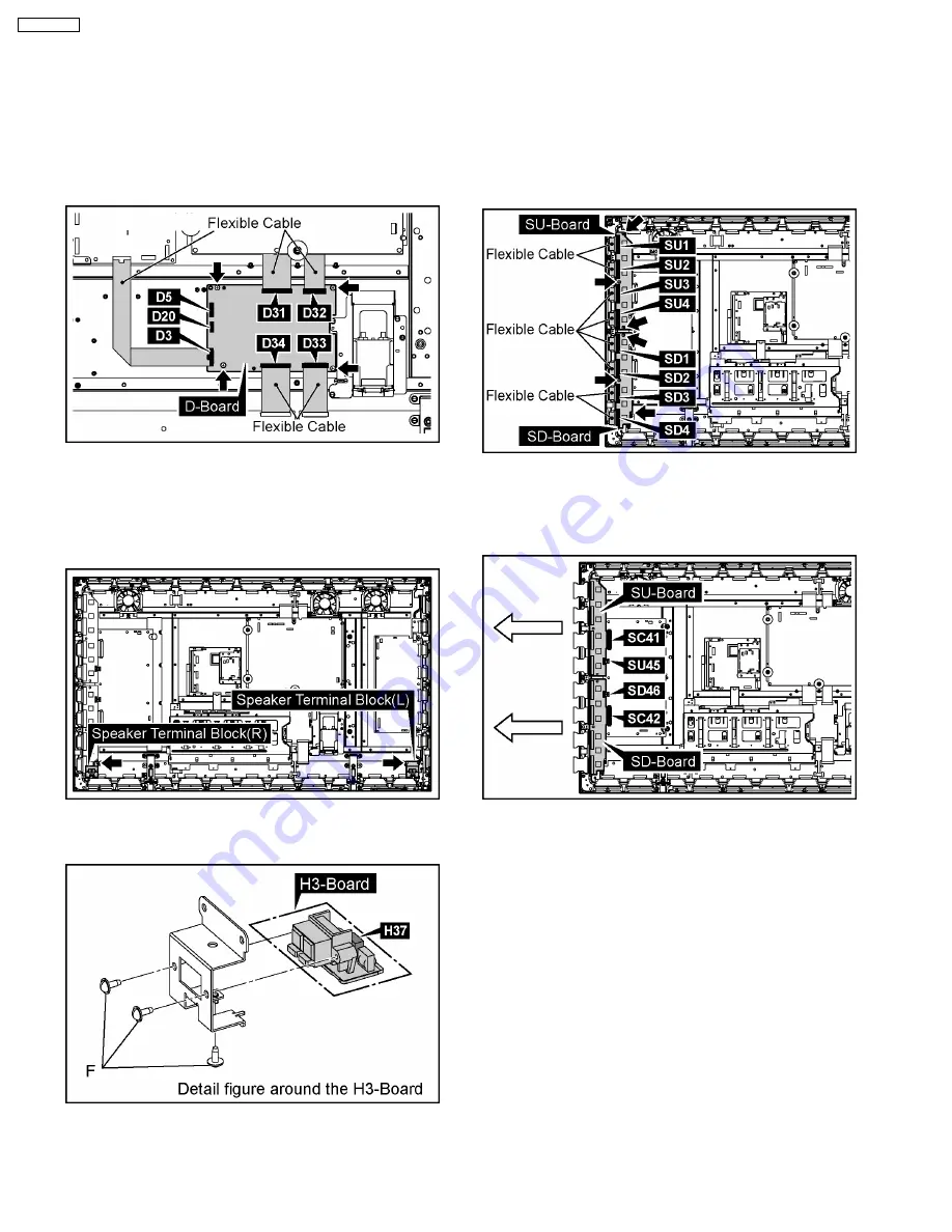
2. Disconnect the coupler(H37).
3. Remove the 3 screws (F) and then remove the H3-Board.
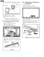
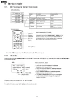
6.12. Removal of the SU-Board and
the SD-Board
1. Remove the Speaker Terminal Block(R).
(Reference to Removal of the H3-Board(L, R))
2. Remove the Flexible Cable from the couplers(SU1, SU2,
SU3, SU4, SD1, SD2, SD3, SD4).
3. Remove the 6 screws.
4. Disconnect the couplers(SU45, SD46).
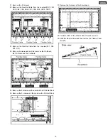
5. Slide the SU-Board and the SD-Board to the left, remove
the SU-Board and the SD-Board from the couplers(SC41,
SC42).
12
TH-50PH9UK
Summary of Contents for TH-50PH9UK
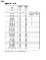
Page 4: ...1 Applicable signals 4 TH 50PH9UK ...
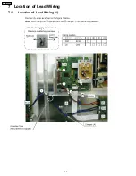
Page 20: ...7 Location of Lead Wiring 7 1 Location of Lead Wiring 1 20 TH 50PH9UK ...
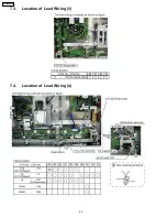
Page 21: ...7 2 Location of Lead Wiring 2 21 TH 50PH9UK ...
Page 22: ...7 3 Location of Lead Wiring 3 7 4 Location of Lead Wiring 4 22 TH 50PH9UK ...
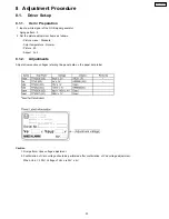
Page 25: ...8 4 Adjustment Volume Location 8 5 Test Point Location 25 TH 50PH9UK ...
Page 29: ...9 2 IIC mode structure following items value is sample data 29 TH 50PH9UK ...
Page 31: ...31 TH 50PH9UK ...
Page 33: ...33 TH 50PH9UK ...
Page 36: ...3 Remarks Above Fan function is operated while the fans are installed 36 TH 50PH9UK ...
Page 39: ...12 Option Setting 39 TH 50PH9UK ...
Page 69: ...14 Block and Schematic Diagram 14 1 Schematic Diagram Notes TH 50PH9UK 69 ...
Page 130: ...NOTE TH 50PH9UK 130 ...
Page 131: ...15 Parts Location 15 1 Exploded View 15 1 1 The main mechanical parts relation 131 TH 50PH9UK ...
Page 133: ...15 3 Cable relation 133 TH 50PH9UK ...
Page 134: ...15 4 Packing summary 134 TH 50PH9UK ...
Page 136: ...17 Replacement Parts List 17 1 Replacement Parts List Notes 136 TH 50PH9UK ...


