


11.2. No Power
37
11.3. No Picture
37
11.4. Local screen failure
38
12 Option Setting
39
13 Conductor Views
41
13.1. P-Board
41
13.2. PB-Board
44
13.3. HA-Board
45
13.4. HU-Board
46
13.5. HX-Board
47
13.6. H3, S1, V1 and V2-Board
48
13.7. J-Board
49
13.8. DA-Board
51
13.9. D-Board
53
13.10. C1-Board
55
13.11. C2-Board
56
13.12. C3-Board
57
13.13. C4-Board
58
13.14. C5-Board
59
13.15. C6-Board
60
13.16. SC-Board
61
13.17. SU-Board
64
13.18. SD-Board
65
13.19. SS-Board
66
13.20. SS2 and SS3-Board
68
14 Block and Schematic Diagram
69
14.1. Schematic Diagram Notes
69
14.2. Main Block Diagram
70
14.3. P-Board Block Diagram
71
14.4. P-Board (1 of 2) Schematic Diagram
72
14.5. P-Board (2 of 2) Schematic Diagram
73
14.6. PB-Board Block and Schematic Diagram
74
14.7. HA-Board Block and Schematic Diagram
75
14.8. HU-Board Block Diagram
76
14.9. HU-Board (1 of 2) Schematic Diagram
77
14.10. HU-Board (2 of 2) Schematic Diagram
78
14.11. HX-Board Block and Schematic Diagram
79
14.12. V1 and V2-Board Block and Schematic Diagram
80
14.13. J-Board (1 of 2) Block Diagram
81
14.14. J-Board (2 of 2) Block Diagram
82
14.15. J-Board (1 of 5) and H3-Board Schematic Diagram
83
14.16. J-Board (2 of 5) Schematic Diagram
84
14.17. J-Board (3 of 5) Schematic Diagram
85
14.18. J-Board (4 of 5) Schematic Diagram
86
14.19. J-Board (5 of 5) Schematic Diagram
87
14.20. DA-Board (1 of 2) Block Diagram
88
14.21. DA-Board (2 of 2) Block Diagram
89
14.22. DA-Board (1 of 6) Schematic Diagram
90
14.23. DA-Board (2 of 6) Schematic Diagram
91
14.24. DA-Board (3 of 6) Schematic Diagram
92
14.25. DA-Board (4 of 6) Schematic Diagram
93
14.26. DA-Board (5 of 6) Schematic Diagram
94
14.27. DA-Board (6 of 6) Schematic Diagram
95
14.28. D-Board (1 of 2) Block Diagram
96
14.29. D-Board (2 of 2) Block Diagram
97
14.30. D-Board (1 of 8) Schematic Diagram
98
14.31. D-Board (2 of 8) Schematic Diagram
99
14.32. D-Board (3 of 8) Schematic Diagram
100
14.33. D-Board (4 of 8) Schematic Diagram
101
14.34. D-Board (5 of 8) Schematic Diagram
102
14.35. D-Board (6 of 8) Schematic Diagram
103
14.36. D-Board (7 of 8) Schematic Diagram
104
14.37. D-Board (8 of 8) Schematic Diagram
105
14.38. C1, C2, C5 and C6-Board Block Diagram
106
14.39. C3, C4, SS, S1, SS2 and SS3-Board Block Diagram
107
14.40. C1-Board (1 of 2) Schematic Diagram
108
14.41. C1-Board (2 of 2) Schematic Diagram
109
14.42. C2-Board (1 of 3) Schematic Diagram
110
14.43. C2-Board (2 of 3) Schematic Diagram
111
14.44. C2-Board (3 of 3) Schematic Diagram
112
14.45. C3-Board (1 of 2) Schematic Diagram
113
14.46. C3-Board (2 of 2) Schematic Diagram
114
14.47. C4-Board (1 of 2) Schematic Diagram
115
14.48. C4-Board (2 of 2) Schematic Diagram
116
14.49. C5-Board (1 of 3) Schematic Diagram
117
14.50. C5-Board (2 of 3) Schematic Diagram
118
14.51. C5-Board (3 of 3) Schematic Diagram
119
14.52. C6-Board (1 of 2) Schematic Diagram
120
14.53. C6-Board (2 of 2) Schematic Diagram
121
14.54. SS, S1, SS2 and SS3-Board Schematic Diagram
122
14.55. SC, SU and SD-Board Block Diagram
123
14.56. SC-Board (1 of 2) Schematic Diagram
124
14.57. SC-Board (2 of 2) Schematic Diagram
125
14.58. SU-Board (1 of 2) Schematic Diagram
126
14.59. SU-Board (2 of 2) Schematic Diagram
127
14.60. SD-Board (1 of 2) Schematic Diagram
128
14.61. SD-Board (2 of 2) Schematic Diagram
129
15 Parts Location
131
15.1. Exploded View
131
15.2. Fan part location enlarged views
132
15.3. Cable relation
133
15.4. Packing summary
134
16 Mechanical Replacement Parts List
135
17 Replacement Parts List
136
17.1. Replacement Parts List Notes
136
17.2. Electrical Replacement Parts List
137
3
TH-50PH9UK
Summary of Contents for TH-50PH9UK
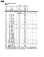
Page 4: ...1 Applicable signals 4 TH 50PH9UK ...
Page 20: ...7 Location of Lead Wiring 7 1 Location of Lead Wiring 1 20 TH 50PH9UK ...
Page 21: ...7 2 Location of Lead Wiring 2 21 TH 50PH9UK ...
Page 22: ...7 3 Location of Lead Wiring 3 7 4 Location of Lead Wiring 4 22 TH 50PH9UK ...
Page 25: ...8 4 Adjustment Volume Location 8 5 Test Point Location 25 TH 50PH9UK ...
Page 29: ...9 2 IIC mode structure following items value is sample data 29 TH 50PH9UK ...
Page 31: ...31 TH 50PH9UK ...
Page 33: ...33 TH 50PH9UK ...
Page 36: ...3 Remarks Above Fan function is operated while the fans are installed 36 TH 50PH9UK ...
Page 39: ...12 Option Setting 39 TH 50PH9UK ...
Page 69: ...14 Block and Schematic Diagram 14 1 Schematic Diagram Notes TH 50PH9UK 69 ...
Page 130: ...NOTE TH 50PH9UK 130 ...
Page 131: ...15 Parts Location 15 1 Exploded View 15 1 1 The main mechanical parts relation 131 TH 50PH9UK ...
Page 133: ...15 3 Cable relation 133 TH 50PH9UK ...
Page 134: ...15 4 Packing summary 134 TH 50PH9UK ...
Page 136: ...17 Replacement Parts List 17 1 Replacement Parts List Notes 136 TH 50PH9UK ...


