

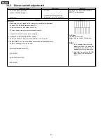


10.3. Power control adjustment
Instrument Name
Connection
Remarks
·
PC (RGB) signal generator
(Leader: VGA/No.9 signal)
·
Wattmeter
·
PC input
·
Connect the AC power of the
adjustment set to the wattmeter.
Set “RGB” at ‘COMPONENT/RGB-IN
SELECT’ in Setup Menu.
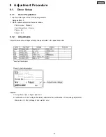
Procedure
Remarks
[condition]
·
Make sure the set is aged for 30 minutes or more before adjustment.
·
Voltage 120V 50/60Hz (variation within 1%)
·
Volume at minimum and screen size at full
·
PC input and picture menu at normalized Dynamic
1.
Connect the set’s AC power to the wattmeter.
2.
Receive the VGA No.9 signal from Leader.
3.
Select the PWRCTL item in Panel APL/ABL in the IIC mode.
4.
Adjust PWRCTL so the set´s power consumption is description below.
Adjust to shift large to small for DAC.
Factory adjustment with OSD
392+8/-15W
BUSCON without OSD
390+8/-15W
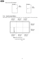
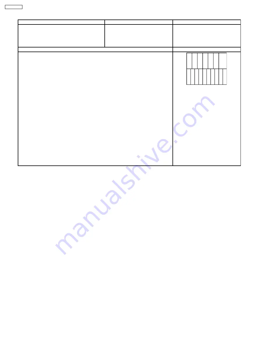
No.9 Signal
Top half: Full color bar
Bottom half: Horizontal 10 steps bar
Notes:
1.
When passing through factory
adjustment mode, the power few
watts which goes down is the
consideration being completed.
2.
Adjust the large number for DAC
when they have 2 adjustment
points.
34
TH-50PH9UK
Summary of Contents for TH-50PH9UK
Page 4: ...1 Applicable signals 4 TH 50PH9UK ...
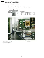
Page 20: ...7 Location of Lead Wiring 7 1 Location of Lead Wiring 1 20 TH 50PH9UK ...
Page 21: ...7 2 Location of Lead Wiring 2 21 TH 50PH9UK ...
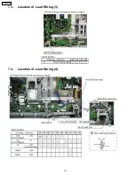
Page 22: ...7 3 Location of Lead Wiring 3 7 4 Location of Lead Wiring 4 22 TH 50PH9UK ...
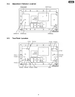
Page 25: ...8 4 Adjustment Volume Location 8 5 Test Point Location 25 TH 50PH9UK ...
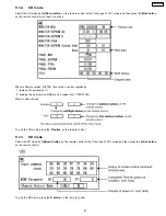
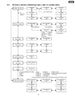
Page 29: ...9 2 IIC mode structure following items value is sample data 29 TH 50PH9UK ...
Page 31: ...31 TH 50PH9UK ...
Page 33: ...33 TH 50PH9UK ...
Page 36: ...3 Remarks Above Fan function is operated while the fans are installed 36 TH 50PH9UK ...
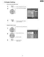
Page 39: ...12 Option Setting 39 TH 50PH9UK ...
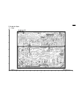
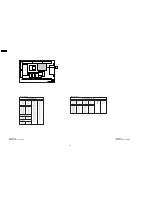
Page 69: ...14 Block and Schematic Diagram 14 1 Schematic Diagram Notes TH 50PH9UK 69 ...
Page 130: ...NOTE TH 50PH9UK 130 ...
Page 131: ...15 Parts Location 15 1 Exploded View 15 1 1 The main mechanical parts relation 131 TH 50PH9UK ...
Page 133: ...15 3 Cable relation 133 TH 50PH9UK ...
Page 134: ...15 4 Packing summary 134 TH 50PH9UK ...
Page 136: ...17 Replacement Parts List 17 1 Replacement Parts List Notes 136 TH 50PH9UK ...