


2.1.1. Leakage Current Cold Check
1. Unplug the AC cord and connect a jumper between the two
prongs on the plug.
2. Measure the resistance value, with an ohmmeter, between
the jumpered AC plug and each exposed metallic cabinet
part on the equipment such as screwheads, connectors,
control shafts, etc. When the exposed metallic part has a
return path to the
chassis, the reading should be between
1M
Ω
and 5.2M
Ω
.
When the exposed metal does not have a return path to
the chassis, the reading must be
.
Figure 1
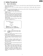
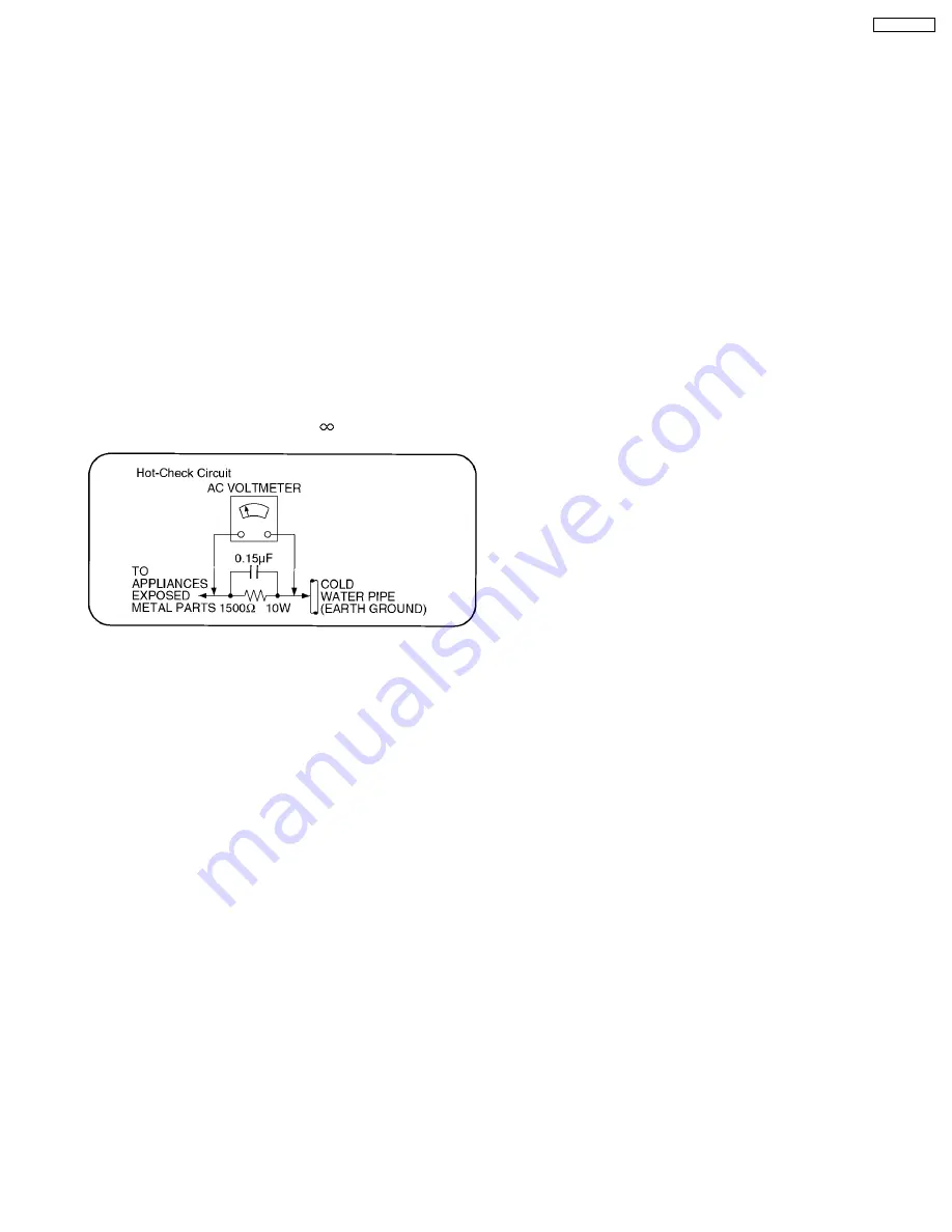
2.1.2. Leakage Current Hot Check (See
Figure 1 .)
1. Plug the AC cord directly into the AC outlet. Do not use an
isolation transformer for this check.
2. Connect a 1.5k
Ω
, 10 watts resistor, in parallel with a 0.15µF
capacitors, between each exposed metallic part on the set
and a good earth ground such as a water pipe, as shown in
Figure 1 .
3. Use an AC voltmeter, with 1000 ohms/volt or more
sensitivity, to measure the potential across the resistor.
4. Check each exposed metallic part, and measure the
voltage at each point.
5. Reverse the AC plug in the AC outlet and repeat each of the
above measurements.
6. The potential at any point should not exceed 0.75 volts
RMS. A leakage current tester (Simpson Model 229 or
equivalent) may be used to make the hot checks, leakage
current must not exceed 1/2 milliamp. In case a
measurement is outsideof the limits specified, there is a
possibility of a shock hazard, and the equipment should be
repaired and rechecked before it is returned to the
customer.
2 Safety Precautions
2.1. General Guidelines
1. When servicing, observe the original lead dress. If a short circuit is found, replace all parts which have been overheated or
damaged by the short circuit.
2. After servicing, see to it that all the protective devices such as insulation barriers, insulation papers shields are properly
installed.
3. After servicing, make the following leakage current checks to prevent the customer from being exposed to shock hazards.
5
TH-50PH9UK
Summary of Contents for TH-50PH9UK
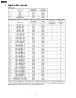
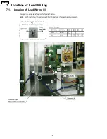
Page 4: ...1 Applicable signals 4 TH 50PH9UK ...
Page 20: ...7 Location of Lead Wiring 7 1 Location of Lead Wiring 1 20 TH 50PH9UK ...
Page 21: ...7 2 Location of Lead Wiring 2 21 TH 50PH9UK ...
Page 22: ...7 3 Location of Lead Wiring 3 7 4 Location of Lead Wiring 4 22 TH 50PH9UK ...
Page 25: ...8 4 Adjustment Volume Location 8 5 Test Point Location 25 TH 50PH9UK ...
Page 29: ...9 2 IIC mode structure following items value is sample data 29 TH 50PH9UK ...
Page 31: ...31 TH 50PH9UK ...
Page 33: ...33 TH 50PH9UK ...
Page 36: ...3 Remarks Above Fan function is operated while the fans are installed 36 TH 50PH9UK ...
Page 39: ...12 Option Setting 39 TH 50PH9UK ...
Page 69: ...14 Block and Schematic Diagram 14 1 Schematic Diagram Notes TH 50PH9UK 69 ...
Page 130: ...NOTE TH 50PH9UK 130 ...
Page 131: ...15 Parts Location 15 1 Exploded View 15 1 1 The main mechanical parts relation 131 TH 50PH9UK ...
Page 133: ...15 3 Cable relation 133 TH 50PH9UK ...
Page 134: ...15 4 Packing summary 134 TH 50PH9UK ...
Page 136: ...17 Replacement Parts List 17 1 Replacement Parts List Notes 136 TH 50PH9UK ...


