background image

36

PICTURE Adjustments


1

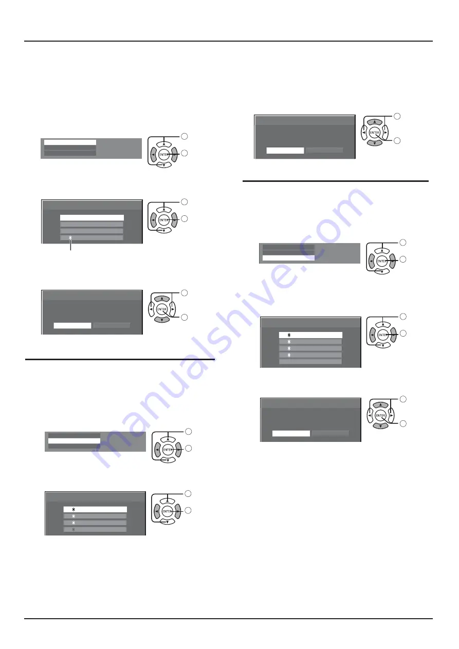
Specify the picture quality in the Picture menu.

2

In the Picture menu, select “Memory save”. 

1

 select

2

 access

3

Select a profile name for saving the picture 
adjustment values. 

Memory save

1. [   ]

2.

3.

[

   ]

4.

[

   ]

[

   ]

MEMORY2

MEMORY3

MEMORY4

MEMORY1

1

 select

4

2

 set

” appears for a profile in which the picture 

adjustments have already been saved.

Select “Ok”. 

Delete the profile.

Memory save

Cancel

Save the adjusted value in ”MEMORY1”

Ok

1

 select

2

 set

Memory load


Memory delete


1

In the Picture menu, select “Memory load”. 

1

 select

2

 access


Note:

$ Loaded profiles are stored in memory according

to the selected input terminal. 

2

Select the profi le to load. 

Memory load

3.

4.

[

   ]

[

   ]

MEMORY2

MEMORY3

MEMORY4

MEMORY1

2. [   ] 

1. [   ]


1

 select

2

 set

1

In the Picture menu, select “Memory delete”. 

1

 select

2

 access

2

Memory delete

Select the profi le to delete. 
To delete all profi les, select “All delete”. 

2. [   ]

3. [   ]

MEMORY2

All delete

MEMORY3

4. [   ]

MEMORY4

1. [   ]

MEMORY1

1

 select

2

 set

3

Select “Ok”. 

Memory delete

Cancel

Delete the ”MEMORY1” data.

Ok

1

 select

2

 set

3

Select “Ok”. 

Memory load

Cancel

Load from ”MEMORY2” data.

Ok

1

 select

2

 set


Memory save

 Memory load


Memory delete

 Memory save


Memory load


Memory delete

 Memory save

 Memory load


Memory delete

Save the picture adjustment values in the MOMORY profile.

Load profiles and apply the picture adjustment values 
in the MOMORY profile.

Memory save

Summary of Contents for TH-55LFV70U

Page 1: ...TH 55LFV70W Before connecting operating or adjusting this product please read these instructions completely Please keep this manual for future reference English Operating Instructions FULL HD LCD Disp...

Page 2: ...labels 54 ECO Mode Settings 55 Wobbling 56 56 Power On Screen Delay 57 Selecting the On Screen Menu Language 57 Day Time settings Set up timer 58 Control Settings 59 Function Button Setting 61 Display...

Page 3: ...heat registers stoves or other apparatus including 9 Do not defeat the safety purpose of the polarized or grounding type plug A polarized plug has two blades with one wider than the other A grounding...

Page 4: ...lacement fuse cover can be purchased from your local Panasonic dealer Do not cut off the mains plug J J J The supplied mains lead and moulded plug are designed to be used with this display to avoid in...

Page 5: ...nel facing upright or downward may cause damage to the internal circuitry Ventilation should not be impeded by covering the ventilation openings with items such as newspapers table cloths and curtains...

Page 6: ...be used Do not handle the power supply plug with wet hands Doing so may cause electric shocks Do not do anything that may damage the power cable When disconnecting the power cable pull on the plug bo...

Page 7: ...ee cloth which has been soaked in pure water or water in which neutral detergent has been diluted 100 times and then wipe it evenly with a dry cloth of the same type until the surface is dry J become...

Page 8: ...ewark NJ 07102 5490 Contact Source Panasonic System Communications Company of North America 1 800 973 4390 This device complies with Part 15 of the FCC Rules and all applicable IC RSS standards Operat...

Page 9: ...Insert batteries note correct polarity and 3 Replace the cover Helpful Hint For frequent remote control users replace old batteries with Alkaline batteries for longer life Precaution on battery use In...

Page 10: ...ess of the mounting bracket and tighten them securely Protective Sheet Table VESA Grid Cautions when installing or moving To prevent this Display from falling G J J Handle with care and with more than...

Page 11: ...and suspending it from the ceiling etc Eyebolt mounting positions Note Suspension and installation should be performed by an installation professional Do not install it using only one eyebolt Use it o...

Page 12: ...plug the AC cord press the two knobs and pull NOTE When disconnecting the AC cord be absolutely sure to disconnect Using the clamper J 1 2 Attach the clamper To remove from the unit pushing both side...

Page 13: ...t 7 DisplayPort IN DisplayPort video input 8 9 DVI D IN 1 DVI D IN 2 DVI D video input 10 11 DIGITAL LINK LAN IN OUT control the Display Alternatively connect to a device that sends video and G 12 PC...

Page 14: ...et J J 60 For daisy chain connection use a straight cable connected to pins numbered 2 through 8 The SERIAL terminal conforms to the RS 232C interface J J computer which is connected to this terminal...

Page 15: ...and Command Parameter Control details PON None Power ON POF None Power OFF AVL Volume 000 100 AMT 0 Audio MUTE OFF 1 Audio MUTE ON IMS None VD1 YP1 HM1 DV1 DV2 PC1 DL1 DP1 UD1 Input select toggle VIDE...

Page 16: ...11 T M D S Clock Shield 2 T M D S Data2 Shield 12 T M D S Clock 3 T M D S Data2 13 CEC 4 T M D S Data1 14 Reserved N C on device 5 T M D S Data1 Shield 15 SCL 6 T M D S Data1 16 SDA 7 T M D S Data0 17...

Page 17: ...port view Pin No Signal Name Pin No Signal Name 1 Lane0 p 11 2 12 Lane3 n 3 Lane0 n 13 4 Lane1 p 14 5 15 AUX_CH n 6 Lane1 n 16 7 Lane2 p 17 AUX_CH p 8 18 Hot Plug Detect 9 Lane2 n 19 DP Power_Return 1...

Page 18: ...nal Name Pin No Signal Name 1 T M D S Data2 13 2 T M D S Data2 14 5 V DC 3 T M D S Data2 Shield 15 4 16 Hot Plug Detect 5 17 T M D S Data0 6 DDC Clock 18 T M D S Data0 7 DDC Data 19 T M D S Data0 Shie...

Page 19: ...19 Connections J __ G J G terminal Display Connection Terminals Control Computer When a Panasonic ET YFB100 is used Computer Video Cassette Recorder DVD Player Notes...

Page 20: ...D Display Second LCD Display Third and subsequent LCD displays ET YFB100 Notes Up to 10 displays can be connected with a daisy chain but the number of the connected displays may be limited by a cable...

Page 21: ...ing connected is not DDC2B compatible you will need to make setting changes to the computer at the time of connection Some PC models cannot be connected to the set There is no need to use an adapter f...

Page 22: ...n Note Additional equipment cables and adapter plugs shown are not supplied with this set R L AUDIO OUT VIDEO OUT RCA BNC Adapter plug DVD Player VCR COMPONENT connection R L AUDIO OUT Y PB PR OUT RCA...

Page 23: ...Additional equipment and cables shown are not supplied with this set Stereophonic sound code audio equipment line in Speaker connection Note While pressing the lever insert the core wire Return the l...

Page 24: ...Power Indicator Green Power switch Power Indicator IR receiver 1 Press the button on the remote control to turn the Display off Power Indicator Red standby 2 Press the button on the remote control to...

Page 25: ...nglish UK Deutsch Fran ais Italiano Espa ol ENGLISH US Day Time settings 1 Z 2 Z Day Time settings Present time SUN 99 99 Set Day SUN Present time 99 99 1 2 Set Day Time settings Present time SUN 99 9...

Page 26: ...IN HDMI DisplayPort DisplayPort input terminal in AV IN DisplayPort DVI D1 DVI D2 DVI D1 or DVI D2 input terminal in DVI D IN Component Component input terminal in COMPONENT VIDEO IN VIDEO VIDEO inpu...

Page 27: ...MUTE button Switch the audio mute ON OFF 3 INPUT button Use this button to select the input source Use this button to make selections while OSD menu is displayed 4 button Increase the adjustment while...

Page 28: ...us Input label Aspect mode Off timer The off timer indicator is displayed only when the off timer has been set Clock display see page 69 12 MUTE button Press to mute the sound Press again to reactivat...

Page 29: ...dly to move through the aspect options 4 3 16 9 Note The aspect mode is memorized separately for each input terminal Aspect mode Picture Enlarged screen Description 4 3 Pictures with a 4 3 aspect rati...

Page 30: ...sic Controls MULTI DISPLAY This displays multi displayed image 1 Switch the Multi display function Press to change to enable or disable the Multi display function AUTO SETUP Q Q J Z is received J Z K...

Page 31: ...e Sound Position Setup 2 Select the item Picture Default Default Picture mode Normal 2 2 10700K Backlight 50 Contrast 50 Brightness 50 Colour 50 Hue 50 Sharpness 50 Gamma Colour temperature Dynamic co...

Page 32: ...etup H position 0 H size 0 V position 0 V size 0 1 1 pixel mode Off Sound menu Sound Default Default Output select SPEAKERS Sound mode Normal Bass 0 Treble 0 Balance 0 Surround Off Setup menu Setup 1...

Page 33: ...ight button to switch between modes Normal Cinema Dynamic Normal For viewing in standard evening lighting environments Dynamic For viewing in brighter environments Cinema For use in viewing tone focus...

Page 34: ...USER2 Adjust Colour Temperature Overwrite USER1 date No Yes Press to select the item for adjustment Press to adjust the each item W B drive R W B drive G W B drive B W B Cutoff R W B Cutoff G W B Cuto...

Page 35: ...t On Picture Default Default Picture mode Normal 2 2 6500K Backlight 75 Contrast 50 Brightness 50 Colour 50 Hue 50 Sharpness 60 Gamma Colour temperature Dynamic contrast 5 Colour enhancement On Pictur...

Page 36: ...n memory according to the selected input terminal 2 Select the profile to load Memory load 3 4 MEMORY2 MEMORY3 MEMORY4 MEMORY1 2 1 1 select 2 set 1 In the Picture menu select Memory delete 1 select 2...

Page 37: ...tup Q Q J Z signal is received J Z Using Remote Control When G J Notes Auto Setup may not work when a cropped or dark image is input In such case switch to a bright image with borders and other object...

Page 38: ...inimized Over Scan Turn image over scan On Off _Q _ _Q _ J K K VIDEO On Off Notes K G J K Mode Adjusts the display size when 1125i or 1125p signal is input Notes K G J Select On when you would like to...

Page 39: ...usts low pitch sound TREBLE Adjusts high pitch sound BALANCE Adjusts left and right volumes SURROUND ON Stereo sound reproduction is active OFF Stereo sound reproduction is not active SETUP Press SETU...

Page 40: ...nema reality Noise reduction Auto MPEG noise reduction Off Input level 0 Signal Component RGB in select RGB Off Cinema reality Auto Sync Noise reduction Off MPEG noise reduction Off XGA mode Input lev...

Page 41: ...splay the Setup menu 1 2 Z 3 Q Z Component Z Note Make setting of the selected input terminal COMPONENT VIDEO IN YUV RGB in select Select to match the signals from the source connected to DVI D IN1 DV...

Page 42: ...ality When On the display attempts to reproduce a more natural interpretation of sources such as movie pictures which are recorded at 24 frames per second If the picture is not stable turn the setting...

Page 43: ...ion Off K Signal Range J J Signal range Full 0 255 _ Video 16 235 G J Full 0 255 Auto J J _ Note J Sync This function operates only during input from PC IN terminal Sync Auto J Note Z Q Z Z G J Z Auto...

Page 44: ...s Monitor out Digital Auto Multi display settings Backup input settings Screensaver Input label ECO mode settings Wobbling Off DIGITAL LINK out Power ON screen delay OSD language English UK Display ID...

Page 45: ...on B Displays which terminal to use for input for serial communication Serial out Displays which terminal to use for output for serial communication Controller ID Terminal A B A Displays the disable e...

Page 46: ...Backup input settings Screensaver Input label ECO mode settings Wobbling Off DIGITAL LINK out Power ON screen delay OSD language English UK Press to select the Multi display settings Multi display se...

Page 47: ...s between displays Suitable for still image display Setting value 0 To hide joints between displays Suitable for moving image display Setting value 100 Location Select the required arrangement number...

Page 48: ...to on the left side Press the button on the remote control Press one of for the tens digit setting Press one of for the units digit setting 4 Notes The numbers in 2 3 and 4 should be set up quickly _...

Page 49: ...tion of video occurs J Notes Switchover time becomes the shortest when the format of the video signal of a main input and a backup input is the same Upon switching to the backup input the video and au...

Page 50: ...I D1 DVI D2 USB PC Component or VIDEO Recall display Pressing the RECALL key displays any of the followings When the main input is being used for viewing and the operating conditions for the Backup In...

Page 51: ...t as Primary Backup Input or Secondary Backup Input Auto switch back mode Sets whether or not to automatically return to the former main input when the former input video initially viewed is restored...

Page 52: ...viewing and the operating conditions for the Backup Input function are met FULL DIGITAL LINK Backup Mode OK When the backup input enabled by the operation of the Backup Input function is being used f...

Page 53: ...to display the Setup menu 1 2 Press to select the Screensaver screen 3 Mode selection Press to select the Mode Off Interval Operates when Periodic Time and Operating Time are set up and those times a...

Page 54: ...ut Digital Auto Multi display settings Backup input settings Screensaver Input label ECO mode settings Wobbling Off DIGITAL LINK out Power ON screen delay OSD language English UK Press to select Input...

Page 55: ...wer supply is turned Off when there is no signal J K _ Note This function is effective during normal viewing one picture screen PC Power management When this function is set to On it operates under th...

Page 56: ...ion is operating part of the screen may appear to be missing DIGITAL LINK out setting Setup 1 2 Signal Display ID settings Monitor out Digital Auto Multi display settings Backup input settings Screens...

Page 57: ...t as a display ID by 0 3 seconds J _ If a display ID is 10 3 seconds Off The display will be turned on at the same time as is pressed 1 to 30 sec Set the power on delay time second After pressing the...

Page 58: ...2 Press to display the Set up TIMER screen or Day Time settings screen Day Time settings Day Time settings Present time SUN 99 99 Set Day SUN Present time 10 00 Press to select DAY or PRESENT TIME 1...

Page 59: ...yer settings Function button settings Display orientation OSD position Upper Right Landscape Menu display duration Menu transparency 20 1 Press to display the Setup menu 2 Press the ENTER key to enter...

Page 60: ...daisy chain Top To connect to the top of daisy chain End To connect to the end of daisy chain Serial response ID all _ received Options OFF a response will not be returned ON a response will be return...

Page 61: ...Function button 3 Function button 4 Function button 8 DVI D1 VIDEO Function button 5 Function button 9 Function button 6 Function button 0 Function button 7 Function button guide DVI D2 USB PC Compone...

Page 62: ...INK 4 DVI D1 5 DVI D2 6 PC 7 Component RGB 8 VIDEO 9 USB 0 2 Press FUNCTION GROUP to switch function group J MEMORYLOAD 1 MEMORY1 2 MEMORY2 3 MEMORY3 4 MEMORY4 5 MEMORY5 6 MEMORY6 7 MEMORY7 8 MEMORY8...

Page 63: ...enu 2 Display orientation Press to display the Display orientation screen DIGITAL LINK status LINK status HDMI status No link No HDMI Signal quality Min 0 dB 0 dB Max DIGITAL LINK status LINK status H...

Page 64: ...menu J 1 4 2 3 Setup 2 2 Set up timer Day Time settings 60 sec Control Settings Network settings USB media player settings Function button settings Display orientation OSD position Upper Right Landsca...

Page 65: ...J Display Name The name of the Display that is shown on the network can be changed LAN Setup See page 66 DIGITAL LINK status See page 67 z See page 67 AMX D D This function allows the Display to be d...

Page 66: ...RT 1 Use to select a digit 2 Use to change a number 3 Press Pressing will cancel the port number change Save Save the current network Setup Each value set for DHCP J G J within the same network DHCP D...

Page 67: ...lours are red yellow or green depending on the number The number is represented by yellow or red if the LAN cable is disconnected or the cable is J connected and the display Signal Quality Display Col...

Page 68: ...ed menu 5 K 2 K 3 K Options Display Serial Number Software Licenses Shipping Press for more than 3 seconds Press to display the Options menu For TH 55LFV70W For TH 55LFV70U Press to adjust the menu G...

Page 69: ...mode of the unit for when the power recovers from failure or after plugging off and in again Normal Power returns in as the same state as before the power interruption Standby Power returns in standby...

Page 70: ...rning Timing No Signal Error No Signal Error Timing Temperature Warning InformationTiming ON 5min ON 10min ON Press ENTER button 2 2 Options Off timer Function Clock Dicplay LAN Control Protcol Inform...

Page 71: ...l Panel Network and Internet Internet Options 2 Set the security level on the Security tab to Default Level Alternatively enable Active scripting from the Custom Level button 1 From the Safari menu cl...

Page 72: ...6 1 Page tab Click these to switch pages 2 Status Click this item and the status of the Display is displayed 3 Display control Click this item to display the Display control page 4 Detailed set up Cl...

Page 73: ...ge Click Status then Network status to display the Status information page J 1 1 J Basic control page To move from another page click Display control then Basic control 1 3 2 4 1 Power On Off control...

Page 74: ...me command used for the serial control 2 Response from the unit is displayed 3 Command is sent and run Note After the settings are changed it may take a while till the display status is displayed Chan...

Page 75: ...ator authority LAN settings 1 Click Detailed set up in the menu 2 Q The settings window appears showing the current settings To change the LAN settings click Change To return to the previous window cl...

Page 76: ...clock to display the Adjust clock page 1 3 2 1 2 3 Button to update time and date settings Notes If the time becomes incorrect immediately after setting the correct time contact the dealer where you...

Page 77: ...wser does not support Flash this page does not appear In this case return to the previous page by clicking Back in the operation page Operation page 2 1 4 5 3 6 7 1 Tools Info Help Switches the pages...

Page 78: ...page of Crestron Connected 4 Network status Displays the setting of LAN DHCP Displays the value in the current setting IpAddres Displays the value in the current setting SubnetMask Displays the value...

Page 79: ...Supported commands Commands to control the unit with PJLink protocol are shown in the table below Command Control Remark POWR Power control Parameter _ J K POWR Power status query Parameter _ J K INP...

Page 80: ...name query Z J INF1 Manufacturer name query Z INF2 Model name query Z _ INFO Other information query Returns version number CLSS Class information query Z PJLink security authentication Web Browser C...

Page 81: ...e input to USB Single Media Player Files are played by a single unit of LFV70 USB Multi Media Player G _ J J J One of the units becomes Master and the others Slaves LFV70 Master LFV70 Slave USB USB Hu...

Page 82: ..._ 2 2 Scenario J J G J J G 2 3 File list J G J J G 2 4 Scenario File list associated terms File name J Contents_video01 wmv J K K __ K __ G The numerical portion can be set from 001 to 999 J Play tim...

Page 83: ...1 Single Media Player Type1 Files will be played in the order they were listed in a scenario J USB media contents filelist dat scenario dat Play contents G J 1 Intoroduction jpg 10 seconds 2 Contents...

Page 84: ...der in which their names appear in USB media Scenario Unnecessary File list Unnecessary USB media contents Play contents G J 1 001_Intoroduction jpg 10 seconds 2 002_Contents_Video1 wmv 10 seconds 3 0...

Page 85: ...seconds 4 L_Contents_Video3 wmv R_Contents_Video1 wmv 1 1 Played for the duration of the play time of L_Contents_Video3 wmv Master side 2 6 USB memory contents check J K Note OSD shows leading error...

Page 86: ...ng Media Player 4 1 For Single Media Player Starting procedure 1 Insert USB memory for Media Player See chapter 2 2 Run a USB memory contents check See chapter 2 6 If an error arises repeat the check...

Page 87: ...enu 2 J Press to display the USB media player settings USB media player Set to enable or disable to USB media player function Resume Play J Z J J J J J detail of error code can be seen USB media playe...

Page 88: ...are program such as a cinema size program with a screen wider than one in the FULL toggle mode blank areas separate from the images are formed at the top and bottom of the screen I can hear sounds com...

Page 89: ...has been switched J G J in the fast moving parts of the images This is normal and not indicative of malfunctioning There may be red spots blue spots green spots and black spots on the screen This is a...

Page 90: ...47 59 94 34 24 12 _ _ 39 55 50 00 51 89 13 _ _ 48 36 60 00 65 00 14 _ _ 56 48 70 07 75 00 15 _ 60 02 75 03 78 75 16 _ 68 68 85 00 94 50 17 _ __ _ 37 64 59 94 53 00 18 _ 53 70 60 00 81 62 19 67 50 75 0...

Page 91: ...50 00 13 50 5 625 576 50i 15 63 50 00 27 00 6 625 575 50p 31 25 50 00 27 00 7 625 576 50p 31 25 50 00 27 00 8 750 720 60p 45 00 60 00 74 25 9 750 720 50p 37 50 50 00 74 25 10 1 125 1 080 60p 67 50 60...

Page 92: ...ttings Monitor out Digital Auto Multi display settings Backup input settings Screensaver Input label ECO mode settings Wobbling Off DIGITAL LINK out Power ON screen delay OSD language English UK Press...

Page 93: ...4PsF PC signals Horizontal scanning frequency 30 110 kHz Vertical scanning frequency 48 120 Hz Connection terminals LAN Z method RJ45 100Base TX VIDEO IN VIDEO AUDIO L R _ 0 5 Vrms AV IN HDMI DisplayP...

Page 94: ...these items please contact your local authorities or dealer and ask for the correct method of disposal This symbol might be used in combination with a chemical symbol In this case it complies with th...

Page 95: ...f your G J G Model Number Serial Number For TH 55LFV70U Panasonic System Communications Company of North America Unit of Panasonic Corporation of North America G K Three Panasonic Way 2F 5 Secaucus NJ...

Reviews: