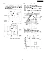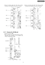
Note:
When assembling the P(P-1)-Board and the P(P-2)- Board,
the position of each hole of the insulation sheets(A, B, C, D)
is set to the position of each hole of the P(P-1)-Board and
the P(P-2)-Board and then assemble them. (
marks
indicate setting positions.)
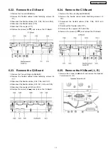
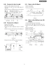
6.3. Remove the PB-Board
1. Unlock the cable clampers to free the cable.
2. Disconnect the couplers (PB30, PB31, PB32, PB33, PB34,
PB35, PB37 and PB38).
3. Remove the screws (×3
) and remove the PB-Board
unit.
4. Remove the screws (×1
) and remove the PB-Board.
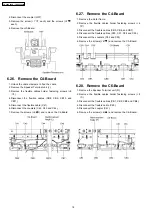
6.4. Remove the D-Board
1. Remove the PB-Board unit.
2. Disconnect the couplers (D3, D5, D20 and D25).
3. Disconnect the flexible cables (D31, D32, D33 and D34).
4. Remove the screws (×1
) and remove the D-Board.
11
TH-65PV500E / TH-65PV500B
Summary of Contents for TH-65PV500E
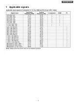
Page 5: ...1 Applicable signals 5 TH 65PV500E TH 65PV500B ...
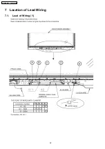
Page 22: ...7 Location of Lead Wiring 7 1 Lead of Wiring 1 22 TH 65PV500E TH 65PV500B ...
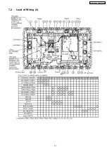
Page 23: ...7 2 Lead of Wiring 2 23 TH 65PV500E TH 65PV500B ...
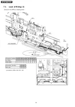
Page 24: ...7 3 Lead of Wiring 3 24 TH 65PV500E TH 65PV500B ...
Page 28: ...8 3 No Picture 28 TH 65PV500E TH 65PV500B ...
Page 31: ...31 TH 65PV500E TH 65PV500B ...
Page 32: ...9 3 Option Description 32 TH 65PV500E TH 65PV500B ...
Page 33: ...33 TH 65PV500E TH 65PV500B ...
Page 42: ...42 TH 65PV500E TH 65PV500B ...
Page 78: ...TH 65PV500E TH 65PV500B 78 ...
Page 79: ...14 Block and Schematic Diagram 14 1 Schematic Diagram Notes TH 65PV500E TH 65PV500B 79 ...
Page 154: ...15 2 Packing Exploded Views 1 154 TH 65PV500E TH 65PV500B ...
Page 155: ...15 3 Packing Exploded Views 2 155 TH 65PV500E TH 65PV500B ...
Page 156: ...15 4 Packing Exploded Views 3 156 TH 65PV500E TH 65PV500B ...


