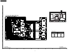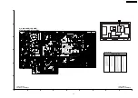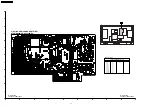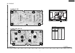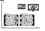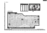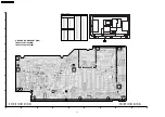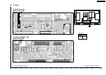
11.3. Sub bright adjustment
Instrument Name
Connection
Remarks
1.
PAL signal generator (or RF)
Connect to the input terminal
User setting: Normal
Procedure
Remarks
·
Color balance adjustment is finished for each signal.
·
Do adjustments in a dark room.
·
Complete the adjustment within 10 minutes after the turn on electricity.
Turn on the power supply again when it is not possible to complete it by aging etc.
1.
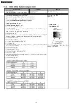
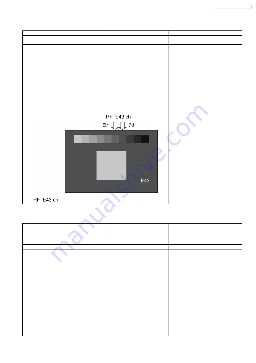
Display the pattern for adjusting subbright from video input.
2.
Pull down SRQ of the panel D-Board to L.
3.
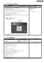
Use "Sub-Bright" in the <Sevice-Menu1> mode to adjust so the 6th section shows up and
the 7th fades away.
Data
Sub-Bright total 12bit data addresses
LSB 8bit A0-016c bit7-0
MSB 4bit A0-016d bit3-0
Picture menu: Dynamic
Color balance: Normal
ASPECT: 16:9
* If using RF ch.E04 or E43
11.4. ABL adjustment
Instrument Name
Connection
Remarks
1.
HD signal emitter (Color bar signal)
2.
Wattmeter
COMPONENT input terminal
Connect
the
AC
power
of
the
adjustment set to the wattmeter.
Procedure
Remarks
·
Make sure the set is aged for 30 minutes or more before adjustment. (Do not switch off
during or after aging.)
·
Voltage 230V 50Hz (variation within 1%)
·
Volume at minimum and screen size at "16:9"
Setting
Component input, dynamic, standard
1.
Connect the set´s AC power to the wattmeter.
2.
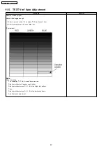
Input the signal (top half: color bar, Bottom half: Horizontal 10 step bar).
3.
Select the "APL MULT" item in the Serivice1.
4.
Adjust APL MULT so the set´s power consumption is
TH-65PV500E
620 ± 20W
TH-65PV500B
629 ± 20W
Remarks
There is a possibility that the adjustment value can do two places, adjust it in that case, that the
value of APL_MULT is large.
39
TH-65PV500E / TH-65PV500B
Summary of Contents for TH-65PV500E
Page 5: ...1 Applicable signals 5 TH 65PV500E TH 65PV500B ...
Page 22: ...7 Location of Lead Wiring 7 1 Lead of Wiring 1 22 TH 65PV500E TH 65PV500B ...
Page 23: ...7 2 Lead of Wiring 2 23 TH 65PV500E TH 65PV500B ...
Page 24: ...7 3 Lead of Wiring 3 24 TH 65PV500E TH 65PV500B ...
Page 28: ...8 3 No Picture 28 TH 65PV500E TH 65PV500B ...
Page 31: ...31 TH 65PV500E TH 65PV500B ...
Page 32: ...9 3 Option Description 32 TH 65PV500E TH 65PV500B ...
Page 33: ...33 TH 65PV500E TH 65PV500B ...
Page 42: ...42 TH 65PV500E TH 65PV500B ...
Page 78: ...TH 65PV500E TH 65PV500B 78 ...
Page 79: ...14 Block and Schematic Diagram 14 1 Schematic Diagram Notes TH 65PV500E TH 65PV500B 79 ...
Page 154: ...15 2 Packing Exploded Views 1 154 TH 65PV500E TH 65PV500B ...
Page 155: ...15 3 Packing Exploded Views 2 155 TH 65PV500E TH 65PV500B ...
Page 156: ...15 4 Packing Exploded Views 3 156 TH 65PV500E TH 65PV500B ...

