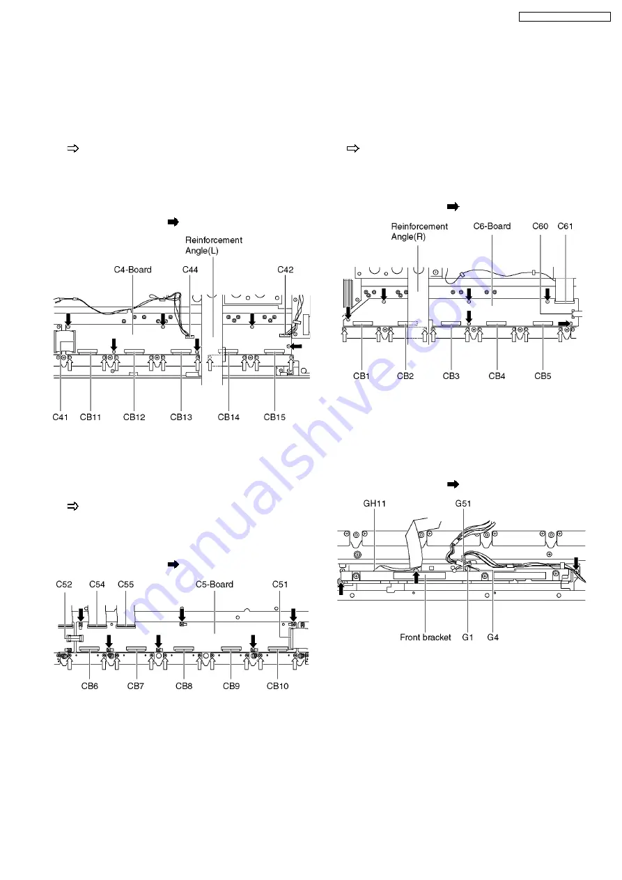
6.31. Remove the C4-Board
1. Remove the Speaker Terminal unit (L). (See section 6.18.)
2. Remove the Esc-fixing metal (A) and (B). (See section 6.19.
and 6.20)
3. Remove the Reinforcement Angle (L). (See section 6.27.)
4. Remove the flexible cables holder fastening screws (×10
).
5. Disconnect the flexible cables (CB11, CB12, CB13, CB14
and CB15).
6. Disconnect the flexible cable (C41).
7. Disconnect the couplers (C42 and C44).
8. Remove the screws (×6
) and remove the C4-Board.
6.32. Remove the C5-Board
1. Remove the tuner unit. (See section 6.7.)
2. Remove the Esc-fixing metal (B). (See section 6.20.)
3. Remove the flexible cables holder fastening screws (×10
).
4. Disconnect the flexible cables (CB6, CB7, CB8, CB9 and
CB10).
5. Disconnect the flexible cables (C51, C52, C54 and C55).
6. Remove the screws (×6
) and remove the C5-Board.
6.33. Remove the C6-Board
1. Remove the Speaker Terminal unit (R). (See section 6.18.)
2. Remove the Esc-fixing metal (A) and (B). (See section 6.19.
and 6.20.)
3. Remove the Reinforcement Angle (R). (See section 6.27.)
4. Remove the flexible cables holder fastening screws (×10
).
5. Disconnect the flexible cables (CB1, CB2, CB3, CB4 and
CB5).
6. Disconnect the flexible cables (C60 and C61).
7. Remove the screws (×6
) and remove the C6-Board.
6.34. Remove the front bracket
1. Remove the Shield cover (A). (See section 6.16.)
2. Unlock the cable clampers to free the cable.
3. Disconnect the couplers (G1, G4 and G51).
4. Disconnect the flexible cable (GH11).
5. Remove the screws (×2
) and remove the front bracket.
19
TH-65PV600A / TH-65PV600M
Summary of Contents for TH-65PV600M
Page 6: ...1 Applicable signals 6 TH 65PV600A TH 65PV600M ...
Page 25: ...8 3 Lead of Wiring 2 25 TH 65PV600A TH 65PV600M ...
Page 26: ...8 4 Lead of Wiring 4 26 TH 65PV600A TH 65PV600M ...
Page 27: ...8 5 Lead of Wiring 5 27 TH 65PV600A TH 65PV600M ...
Page 31: ...9 4 No Picture 31 TH 65PV600A TH 65PV600M ...
Page 34: ...34 TH 65PV600A TH 65PV600M ...
Page 35: ...10 3 Option Description 35 TH 65PV600A TH 65PV600M ...
Page 36: ...36 TH 65PV600A TH 65PV600M ...
Page 39: ...11 4 Adjustment Volume Location 11 5 Test Point Location 39 TH 65PV600A TH 65PV600M ...
Page 48: ...48 TH 65PV600A TH 65PV600M ...
Page 83: ...15 Schematic and Block Diagram 15 1 Schematic Diagram Notes TH 65PV600A TH 65PV600M 83 ...
Page 164: ...16 2 Packing Exploded View 1 164 TH 65PV600A TH 65PV600M ...
Page 165: ...16 3 Packing Exploded View 2 165 TH 65PV600A TH 65PV600M ...
Page 166: ...16 4 Packing Exploded View 3 166 TH 65PV600A TH 65PV600M ...


