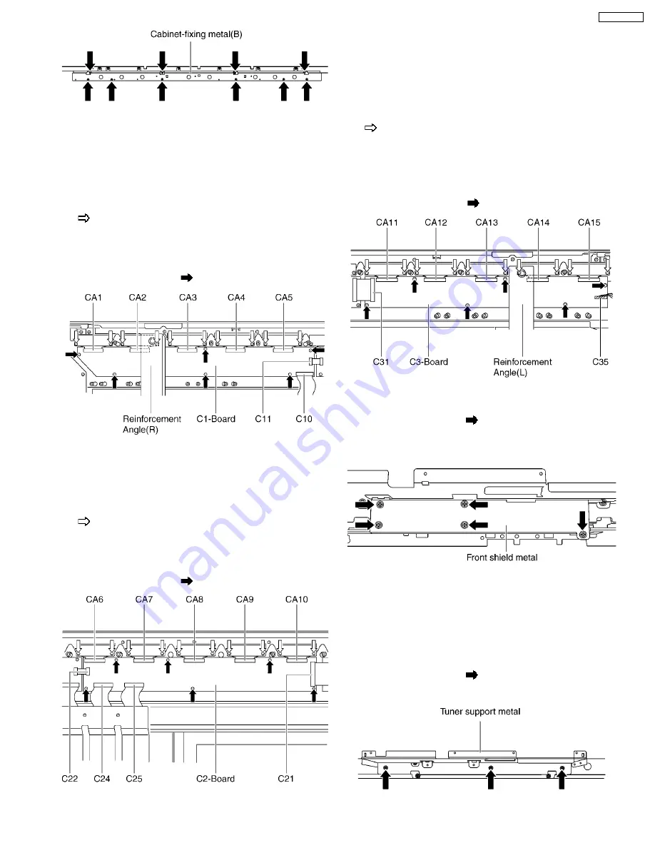
6.23. Remove the C1-Board
1. Remove the Fan unit (R). (See section 6.19.)
2. Remove the Cabinet-fixing metal (A) and (B). (See section
6.21. and 6.22.)
3. Remove the Reinforcement Angle (R). (See section 6.18.)
4. Remove the flexible cables holder fastening screws (×10
).
5. Disconnect the flexible cables (CA1, CA2, CA3, CA4 and
CA5).
6. Disconnect the flexible cables (C10 and C11).
7. Remove the screws (×6
) and remove the C1-Board.
6.24. Remove the C2-Board
1. Remove the Fan unit (L). (See section 6.20.)
2. Remove the Cabinet-fixing metal (B). (See section 6.22.)
3. Remove the flexible cables holder fastening screws (×10
).
4. Disconnect the flexible cables (CA6, CA7, CA8, CA9, and
CA10).
5. Disconnect the flexible cables (C21, C22, C24 and C25).
6. Remove the screws (×6
) and remove the C2-Board.
6.25. Remove the C3-Board
1. Remove the Fan unit (L). (See section 6.20.)
2. Remove the Cabinet-fixing metal (A) and (B). (See section
6.21. and 6.22.)
3. Remove the Reinforcement Angle (L). (See section 6.18.)
4. Remove the flexible cables holder fastening screws (×10
).
5. Disconnect the flexible cables (CA11, CA12, CA13, CA14
and CA15).
6. Disconnect the flexible cable (C31).
7. Disconnect the coupler (C35).
8. Remove the screws (×6
) and remove the C3-Board.
6.26. Remove the Front Shield metal
1. Remove the screw (×5
).
2. Remove the Front shield metal.
6.27. Remove the Tuner Support
metal
1. Unlock the cable clampers to free the cable.
2. Disconnect the connector (H51). (See section 6.5.)
3. Disconnect the flexible cable (DG11). (See section 6.5.)
4. Remove the screw (×3
).
5. Remove the Tuner support metal.
17
TH-65PZ750U
Summary of Contents for TH-65PZ750U
Page 5: ...1 Applicable signals 5 TH 65PZ750U ...
Page 24: ...8 Location of Lead Wiring 8 1 Lead of Wiring 1 24 TH 65PZ750U ...
Page 25: ...8 2 Lead of Wiring 2 25 TH 65PZ750U ...
Page 26: ...8 3 Lead of Wiring 3 26 TH 65PZ750U ...
Page 27: ...8 4 Lead of Wiring 4 27 TH 65PZ750U ...
Page 28: ...8 5 Lead of Wiring 5 28 TH 65PZ750U ...
Page 32: ...9 4 No Picture 32 TH 65PZ750U ...
Page 39: ...11 4 Adjustment Volume Location 11 5 Test Point Location 39 TH 65PZ750U ...
Page 41: ...41 TH 65PZ750U ...
Page 77: ...15 Schematic and Block Diagram 15 1 Schematic Diagram Note TH 65PZ750U 77 ...
Page 157: ...16 Exploded Views Replacement Parts List 16 1 Exploded Views 157 TH 65PZ750U ...
Page 158: ...16 2 Packing Exploded Views Accessories 158 TH 65PZ750U ...
Page 159: ...16 3 Replacement Parts List Notes 159 TH 65PZ750U ...


