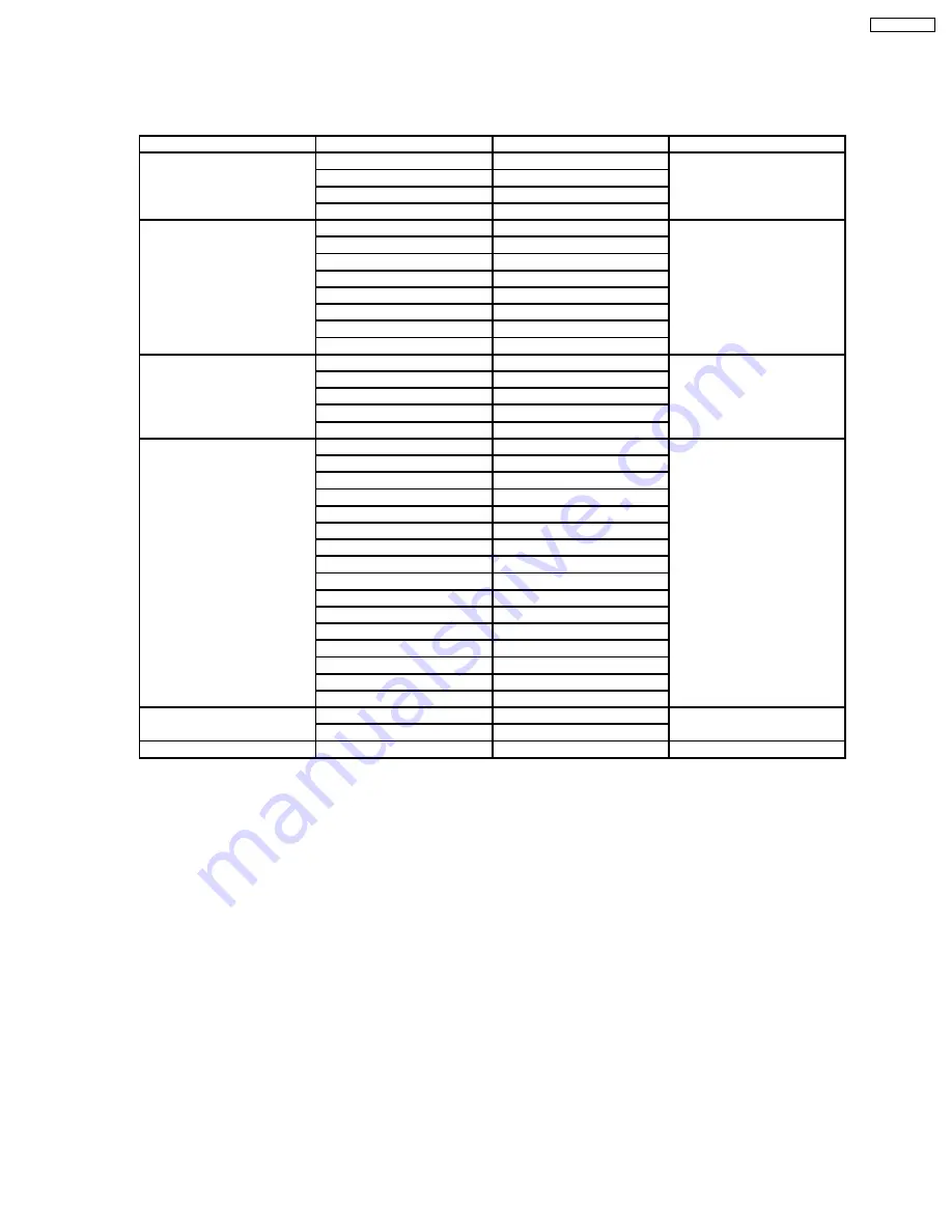
10.1.2. Contents of adjustment mode
·
Value is shown as a hexadecimal number.
·
Preset value differs depending on models.
·
After entering the adjustment mode, take note of the value in each item before starting adjustment.
Main item
Sub item
Sample Data
Remark
ADJUST
CONTRAST
000
COLOR
3F
TINT
03
SUB-BRT
800
WB-ADJ
R-CUT
80
G-CUT
80
B-CUT
80
R-DRV
FC
G-DRV
E6
B-DRV
E9
ALL-CUT
80
ALL-DRV
FC
OPTION
BOOT
ROM
Factory Preset
STBY-SET
00
Emergency
ON
CLK MODE
00
CLOCK
000
AGING
RGBW
COUNT
ALL WHITE
ALL RED
ALL GREEN
ALL BLUE
ON/OFF
RAMP WHITE
RAMP RED
RAMP GREEN
RAMP BLUE
1% WINDOW
COLOR BAR
A-ZONE B-ZONE/4 TRIO
SCROLL
WHITE FLAME
RM-SET
CODE
A
Fixed
SRV-TOOL
-
See next
10.1.3. How to exit
Switch off the power with the [POWER] button on the main unit or the [POWER] button on the remote control.
35
TH-65PZ750U
Summary of Contents for TH-65PZ750U
Page 5: ...1 Applicable signals 5 TH 65PZ750U ...
Page 24: ...8 Location of Lead Wiring 8 1 Lead of Wiring 1 24 TH 65PZ750U ...
Page 25: ...8 2 Lead of Wiring 2 25 TH 65PZ750U ...
Page 26: ...8 3 Lead of Wiring 3 26 TH 65PZ750U ...
Page 27: ...8 4 Lead of Wiring 4 27 TH 65PZ750U ...
Page 28: ...8 5 Lead of Wiring 5 28 TH 65PZ750U ...
Page 32: ...9 4 No Picture 32 TH 65PZ750U ...
Page 39: ...11 4 Adjustment Volume Location 11 5 Test Point Location 39 TH 65PZ750U ...
Page 41: ...41 TH 65PZ750U ...
Page 77: ...15 Schematic and Block Diagram 15 1 Schematic Diagram Note TH 65PZ750U 77 ...
Page 157: ...16 Exploded Views Replacement Parts List 16 1 Exploded Views 157 TH 65PZ750U ...
Page 158: ...16 2 Packing Exploded Views Accessories 158 TH 65PZ750U ...
Page 159: ...16 3 Replacement Parts List Notes 159 TH 65PZ750U ...


