12 White Balance Adjustment
12.1. White balance adjustment
Name of measuring instrument
Connection
Remarks
·
W/B pattern
·
Color analyzer
(Minolta CA-100 or equivalent)
Component input
Panel surface
Procedure
Remarks
·
Ensure aging is adequate.
·
Make sure the front panel to be used on the final set is fitted.
·
Make sure a color signal is not being shown before adjustment.
·
Put the color analyzer where there is little color variation.
1.
Output a white balance pattern.
2.
Check that the color temperature is “Cool”.
3.
Set to serviceman mode, WB-ADJ.
4. Set “R-CUT” “G-CUT” “B-CUT” the values written in table 1.
5.
Attach the sensor of color analyzer to he center of highlight window.
6.
Fix G drive at C0h and adjust “B-DRV” and “R-DRV” so x, y value of color analyzer
become the “Color temperature High” in table 2.
7.
Increase RGB together so the maximum drive value in RGB becomes FCh. That is,
set “ALL DRIVE” to FCh.
8. Set color temperature to “Normal”.
9.
Set “R-CUT” “G-CUT” “B-CUT” the values written in table 1.
10. Attach the sensor of color analyzer to the center of highlight window.
11. Fix G drive at C0h and adjust “B-DRV” and “R-DRV” so x, y value of color analyzer
become the “Color temperature Mid” in table 2.
12. Increase RGB together so the maximum drive value in RGB becomes FCh. That is,
set “ALL DRIVE” to FCh.
13. Set color temperature to “Warm”.
14. Set “R-CUT” “G-CUT” “B-CUT” the values written in table 1.
15. Attach the sensor of color analyzer to the center of highlight window.
16. Fix G drive at C0h and adjust “B-DRV” and “R-DRV” so x, y value of color analyzer
become the “Color temperature Low” in table 2.
17. Increase RGB together so the maximum drive value in RGB becomes FCh. That is,
set “ALL DRIVE” to FCh.
18. Set color temperature to “Cool”.
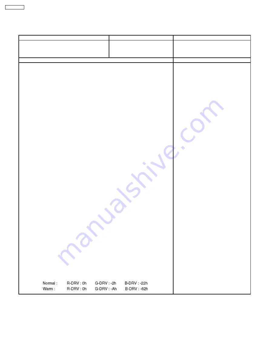
[ adjustment of “Normal” “Warm” by data shift from “Cool” adjust. ]
For “Normal” “Warm” adjustment, set values that the adjusted value of “Cool”
plus the figures wrote below.
19. Copy values adjusted by HD pattern to the NTSC data area of EEPROM.
40
TH-65PZ750U
Summary of Contents for TH-65PZ750U
Page 5: ...1 Applicable signals 5 TH 65PZ750U ...
Page 24: ...8 Location of Lead Wiring 8 1 Lead of Wiring 1 24 TH 65PZ750U ...
Page 25: ...8 2 Lead of Wiring 2 25 TH 65PZ750U ...
Page 26: ...8 3 Lead of Wiring 3 26 TH 65PZ750U ...
Page 27: ...8 4 Lead of Wiring 4 27 TH 65PZ750U ...
Page 28: ...8 5 Lead of Wiring 5 28 TH 65PZ750U ...
Page 32: ...9 4 No Picture 32 TH 65PZ750U ...
Page 39: ...11 4 Adjustment Volume Location 11 5 Test Point Location 39 TH 65PZ750U ...
Page 41: ...41 TH 65PZ750U ...
Page 77: ...15 Schematic and Block Diagram 15 1 Schematic Diagram Note TH 65PZ750U 77 ...
Page 157: ...16 Exploded Views Replacement Parts List 16 1 Exploded Views 157 TH 65PZ750U ...
Page 158: ...16 2 Packing Exploded Views Accessories 158 TH 65PZ750U ...
Page 159: ...16 3 Replacement Parts List Notes 159 TH 65PZ750U ...


