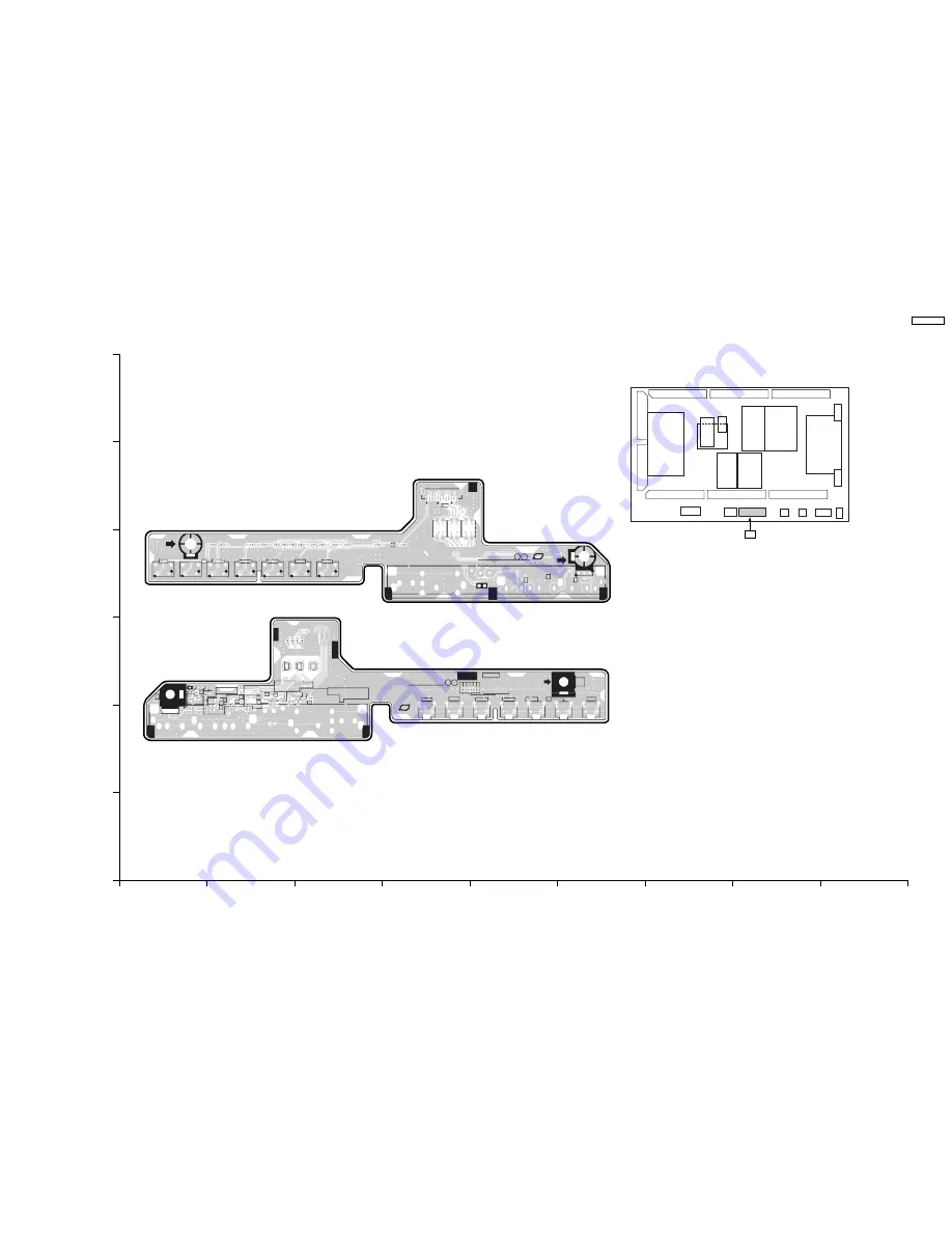
14.2. G-Board
A
B
C
D
E
F
G
H
I
1
2
3
4
5
6
L3713
JK3701
C3702
C3704
C3706
C3708
C3714
D3701
D3702
D3703
D3704
D3705
D3706
D3707
D3708
D3709
D3710
D3711
R3714
R3716
R3717
R3718
R3719
R3720
R3721
R3732
R3736
R3737
R3738
R3739
R3740
R3741
SW3751
SW3753
SW3754
SW3755
SW3756
SW3757
SW3758
FL3715
FL3716
FL3717
JS3700
JS3701
JS3702
JS3711
JS3712
JS3713
JS3714
JS3715
JS3716
JS3717
ZA3701
ZA3702
AG
AE
AD
AC
AB
AF
PbF
CH.UP
CH.DN
VOL.UP
VOL.DN
TV/VTR
OK
G
1
TNPA4306
USA
MENU
R
L
V
R
L
V
SUFFIX.
1
2
3 4
1
2
3 4
1
2
3 4
JK3701
G51
L3750
C3750
SW3751
SW3753
SW3754
SW3755
SW3756
SW3757
D3750
SW3758
R3750
R3751
R3752
R3753
R3754
R3755
R3756
R3758
R3765
R3766
R3767
R3768
FL3710
FL3711
FL3712
ZA3701
TNPA4306
1 G
PbF
CH.UP
CH.DN
VOL.UP
VOL.DN
OK
USA
MENU
TV/VTR
R
L
V
1
12
REVERSE
FOR
SUFFIX.
SEE
TH-65PZ750U
G-BOARD TNPA4306ABS
G-BOARD (COMPONENT SIDE)
TNPA4306ABS
G-BOARD (FOIL SIDE)
TNPA4306ABS
TH-65PZ750U
G-BOARD TNPA4306ABS
G
TH-65PZ750U
49
Summary of Contents for TH-65PZ750U
Page 5: ...1 Applicable signals 5 TH 65PZ750U ...
Page 24: ...8 Location of Lead Wiring 8 1 Lead of Wiring 1 24 TH 65PZ750U ...
Page 25: ...8 2 Lead of Wiring 2 25 TH 65PZ750U ...
Page 26: ...8 3 Lead of Wiring 3 26 TH 65PZ750U ...
Page 27: ...8 4 Lead of Wiring 4 27 TH 65PZ750U ...
Page 28: ...8 5 Lead of Wiring 5 28 TH 65PZ750U ...
Page 32: ...9 4 No Picture 32 TH 65PZ750U ...
Page 39: ...11 4 Adjustment Volume Location 11 5 Test Point Location 39 TH 65PZ750U ...
Page 41: ...41 TH 65PZ750U ...
Page 77: ...15 Schematic and Block Diagram 15 1 Schematic Diagram Note TH 65PZ750U 77 ...
Page 157: ...16 Exploded Views Replacement Parts List 16 1 Exploded Views 157 TH 65PZ750U ...
Page 158: ...16 2 Packing Exploded Views Accessories 158 TH 65PZ750U ...
Page 159: ...16 3 Replacement Parts List Notes 159 TH 65PZ750U ...


