TH-L32EM5
D
18
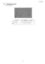
7.4.
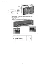
Fixing P Board and A Board
1. Fixing P-print to LCD panel.
2. Fix Key Btn to P-print.
3. Fixing chassis bracket A-pcb ( 2pc ) TO A-print and fix to LCD panel.
4. Fixing Side AV Bracket to A-print.
5. Fix metal bracket bottom.
6. Fix bottom cover.
7. Fix above part with screw.
No Description
Qty
UOM
Remarks
01
SCREW
11
PC
60 ± 10 N·cm
02
BOTTOM METAL
1
PC
03
CONTROL BUTTON
1
PC
04
SIDE AV BRACKET
1
PC
05
CHASSIS BRACKET A-PCB
2
PC
06
BOTTOM COVER
1
PC
Summary of Contents for TH-L32EM5D
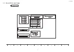
Page 23: ...TH L32EM5D 23 11 Schematic Diagram 11 1 Schematic Diagram Notes ...
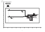
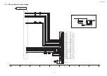
Page 34: ...TH L32EM5D 34 11 12 K Board Schematic Diagram 6 5 4 3 2 1 A B C D E F G H I ...
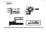
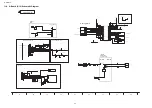
Page 35: ...TH L32EM5D 35 11 13 P Board Schematic Diagram 6 5 4 3 2 1 A B C D E F G H I ...
Page 50: ...Model No TH L32EM5D Parts Location ...


