TH-L37D25A
32
8.3.
Picture level adjustment (RF)
8.4.
Picture level adjustment (VIDEO)
8.5.
Picture level adjustment (YUV)
Instrument Name
Remarks
1. REMOTE TRANSMITTER
2. Ex. Signal (Sprit color bar)
Adjustment or Inspection Procedure
Remarks
<procedure>
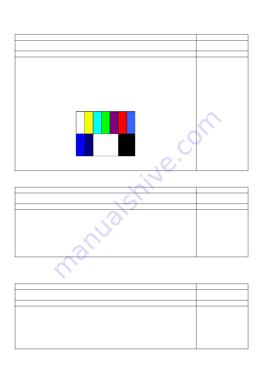
1. Receive the Sprit color bar.
(Screen mode: ZOOM or FULL Picture mode: DYNAMIC AI: OFF AI Picture: OFF)
*BACK LIGHT +30
<Inspection>
1. Enter Service mode, and select MAIN_ADJ PICTURE.
Volume UP/DOWN key makes GAIN displayed under PICTURE to set.
Pushing the remote controller [OK] key for about 3 seconds, GAIN is suited
to the adjustment value automatically.
(The Sprit Color Bar Pattern)
Instrument Name
Remarks
1. REMOTE TRANSMITTER
2. Video signal generator (100% Color bar)
Adjustment or Inspection Procedure
Remarks
<procedure>
1. Receive 100% Color bar.
(ASPECT: ZOOM or FULL, Picture mode: VIVID, AI Picture: OFF)
* BACK LIGHT MAX VALUE
<Inspection>
1. Enter Service mode, and select ADJUST CONTRAST.
Volume UP/DOWN key makes GAIN value displayed on the right of CONTRAST to set.
Pushing the remote controller [OK] key for about 3 seconds, GAIN is suited to the adjustment value
automatically.
Instrument Name
Remarks
1. REMOTE TRANSMITTER
2. Component Video signal generator (100% Color bar 1080i)
Adjustment or Inspection Procedure
Remarks
<procedure>
1. Receive 100% Color bar.
(ASPECT: ZOOM or FULL, Picture mode: VIVID, AI Picture: OFF)
* BACK LIGHT MAX VALUE
<Inspection>
1. Enter Service mode, and select ADJUST CONTRAST.
Volume UP/DOWN key makes GAIN value displayed on the right of CONTRAST to set.
Pushing the remote controller [OK] key for about 3 seconds, GAIN is suited to the adjustment value
automatically.
Summary of Contents for TH-L37D25A Viera
Page 15: ...TH L37D25A 15 7 2 AC Cord Dressing 2 ...
Page 17: ...TH L37D25A 17 7 4 AC Cord Bracket Installation Put on AC CORD BRACKET on cabinet and screw it ...
Page 18: ...TH L37D25A 18 7 5 Control Panel Assembly Put CONTROL PANEL ASSY on cabinet ...
Page 24: ...TH L37D25A 24 7 11 SP Unit Installation Put SP UNIT L and SP UNIT R on CABINET ...
Page 39: ...TH L37D25A 39 11 Schematic Diagram 11 1 Schematic Diagram Notes ...
Page 40: ...TH L37D25A 40 11 2 A Board 1 17 Schematic Diagram 6 5 4 3 2 1 A B C D E F G H I ...
Page 41: ...TH L37D25A 41 11 3 A Board 2 17 Schematic Diagram 6 5 4 3 2 1 A B C D E F G H I ...
Page 42: ...TH L37D25A 42 11 4 A Board 3 17 Schematic Diagram 6 5 4 3 2 1 A B C D E F G H I ...
Page 43: ...TH L37D25A 43 11 5 A Board 4 17 Schematic Diagram 6 5 4 3 2 1 A B C D E F G H I ...
Page 44: ...TH L37D25A 44 11 6 A Board 5 17 Schematic Diagram 6 5 4 3 2 1 A B C D E F G H I ...
Page 45: ...TH L37D25A 45 11 7 A Board 6 17 Schematic Diagram 6 5 4 3 2 1 A B C D E F G H I ...
Page 46: ...TH L37D25A 46 11 8 A Board 7 17 Schematic Diagram 6 5 4 3 2 1 A B C D E F G H I ...
Page 47: ...TH L37D25A 47 11 9 A Board 8 17 Schematic Diagram 6 5 4 3 2 1 A B C D E F G H I ...
Page 48: ...TH L37D25A 48 11 10 A Board 9 17 Schematic Diagram 6 5 4 3 2 1 A B C D E F G H I ...
Page 49: ...TH L37D25A 49 11 11 A Board 10 17 Schematic Diagram 6 5 4 3 2 1 A B C D E F G H I ...
Page 50: ...TH L37D25A 50 11 12 A Board 11 17 Schematic Diagram 6 5 4 3 2 1 A B C D E F G H I ...
Page 51: ...TH L37D25A 51 11 13 A Board 12 17 Schematic Diagram 6 5 4 3 2 1 A B C D E F G H I ...
Page 52: ...TH L37D25A 52 11 14 A Board 13 17 Schematic Diagram 6 5 4 3 2 1 A B C D E F G H I ...
Page 53: ...TH L37D25A 53 11 15 A Board 14 17 Schematic Diagram 6 5 4 3 2 1 A B C D E F G H I ...
Page 54: ...TH L37D25A 54 11 16 A Board 15 17 Schematic Diagram 6 5 4 3 2 1 A B C D E F G H I ...
Page 55: ...TH L37D25A 55 11 17 A Board 16 17 Schematic Diagram 6 5 4 3 2 1 A B C D E F G H I ...
Page 56: ...TH L37D25A 56 11 18 A Board 17 17 Schematic Diagram 6 5 4 3 2 1 A B C D E F G H I ...
Page 57: ...TH L37D25A 57 11 19 V Board Schematic Diagram 6 5 4 3 2 1 A B C D E F G H I ...
Page 58: ...TH L37D25A 58 11 20 TC Board 1 6 Schematic Diagram 6 5 4 3 2 1 A B C D E F G H I ...
Page 59: ...TH L37D25A 59 11 21 TC Board 2 6 Schematic Diagram 6 5 4 3 2 1 A B C D E F G H I ...
Page 60: ...TH L37D25A 60 11 22 TC Board 3 6 Schematic Diagram 6 5 4 3 2 1 A B C D E F G H I ...
Page 61: ...TH L37D25A 61 11 23 TC Board 4 6 Schematic Diagram 6 5 4 3 2 1 A B C D E F G H I ...
Page 62: ...TH L37D25A 62 11 24 TC Board 5 6 Schematic Diagram 6 5 4 3 2 1 A B C D E F G H I ...
Page 63: ...TH L37D25A 63 11 25 TC Board 6 6 Schematic Diagram 6 5 4 3 2 1 A B C D E F G H I ...
Page 81: ...Model No TH L37D25A Parts Location ...
Page 82: ...Model No TH L37D25A Packing Exploded View 1 ...


