38
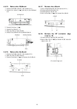
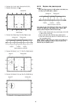
2. Remove the Corner metal. (See section 8.2.29.)
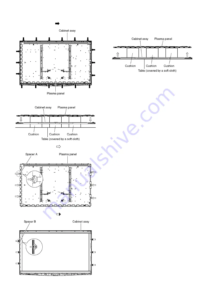
3. Remove the screws (
×
18 ).
4. Remove the Cabinet assy from the Plasma panel.
5. Remove the Spacer A (
×
6
) from the Plasma panel.
6. Remove the Spacer B (
×
6
) from the Cabinet assy.
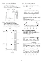
8.2.31. Replace the plasma panel
Caution:
Place the Plasma panel on a flat surface of a table (cov-
ered by a soft cloth) and a cushion.
A new plasma panel itself without Cabinet assy is fragile.
To avoid the damage to new plasma panel, carry a new
plasma panel taking hold of the Cabinet assy.
1. Place a carton box packed a new plasma panel on the flat
surface of the work bench.
2. Open a box and without taking a new plasma panel.
3. Attach the cabinet assy and each P.C.Board and so on, to
the new plasma panel.
*When fitting the cabinet assy, be careful not to allow any
debris, dust or handling residue to remain between the
cabinet assy and plasma panel.
Summary of Contents for TH-P54Z1D
Page 24: ...24 6 4 No Picture ...
Page 41: ...41 9 1 4 Adjustment Volume Location 9 1 5 Test Point Location ...
Page 42: ...42 ...
Page 54: ...54 11 3 Wiring Display unit 1 11 4 Wiring Display unit 2 ...
Page 55: ...55 11 5 Wiring Display unit 3 11 6 Wiring Display unit 4 ...
Page 56: ...56 11 7 Wiring Display unit 5 11 8 Wiring Display unit 6 ...
Page 57: ...57 12 Schematic Diagram 12 1 Schematic Diagram Note ...
Page 146: ...146 ...
Page 148: ...148 14 1 2 Exploded View 2 Display unit ...
Page 149: ...149 14 1 3 Exploded View 3 Display unit ...
Page 150: ...150 14 1 4 Packing 1 ...
Page 151: ...151 14 1 5 Packing 2 ...
Page 152: ...152 14 1 6 Packing 3 ...
Page 153: ...153 14 1 7 Packing 4 Pedestal stand ...
Page 154: ...154 14 1 8 Packing 5 ...
Page 155: ...155 14 1 9 Packing 6 ...
Page 156: ...156 14 1 10 Packing 7 ...
Page 162: ...162 14 2 Electrical Replacement Parts List 14 2 1 Replacement Parts List Notes ...


