23
8 Disassembly and Assembly Instructions
8.1.
Remove the Rear cover
1. See PCB Layout (Section 3)
8.2.
Remove the AC inlet
Caution:
To remove P.C.B. wait 1 minute after power was off for dis-
charge from electrolysis capacitors.
1. Unlock the cable clampers to free the cable.
2. Disconnect the connector (P9).
3. Remove the screw (
×
1
) and remove the AC inlet.
8.3.
Remove the P-Board
Caution:
To remove P.C.B. wait 1 minute after power was off for dis-
charge from electrolysis capacitors.
1. Unlock the cable clampers to free the cable.
2. Disconnect the connectors (P51-P52, P53-P54 and P55-
P56).
3. Disconnect the connectors (P2, P6, P7, P9, P11 and
P35).
4. Remove the screws (
×
9
) and remove the P(MAIN)-
Board.
5. Remove the screws (
×
6
) and remove the P(SUB)-
Board.
8.4.
Remove the Side terminal
cover and the Rear AV panel
1. Remove the claws (
×
2 ).
2. Remove the Side terminal cover.
3. Remove the screws (
×
2 ,
×
3 ).
4. Remove the Rear AV panel.
Summary of Contents for TH-P58S20M
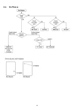
Page 20: ...20 6 4 No Picture ...
Page 38: ...38 ...
Page 40: ...40 11 3 Wiring 2 ...
Page 41: ...41 11 4 Wiring 3 ...
Page 42: ...42 11 5 Wiring 4 ...
Page 43: ...43 11 6 Wiring 5 11 7 Wiring 6 ...
Page 44: ...44 ...
Page 45: ...45 12 Schematic Diagram 12 1 Schematic Diagram Note ...
Page 83: ...83 A B C D E F G H I 1 2 3 4 5 6 P MAIN BOARD COMPONENT SIDE ETX2MM812MSM ...
Page 96: ...96 ...
Page 98: ...98 14 1 2 Exploded View 2 ...
Page 99: ...99 14 1 3 Packing 1 ...
Page 100: ...100 14 1 4 Packing 2 ...
Page 101: ...101 14 1 5 Packing 3 ...
Page 105: ...105 14 2 Electrical Replacement Parts List 14 2 1 Replacement Parts List Notes ...


