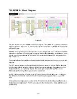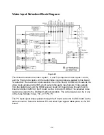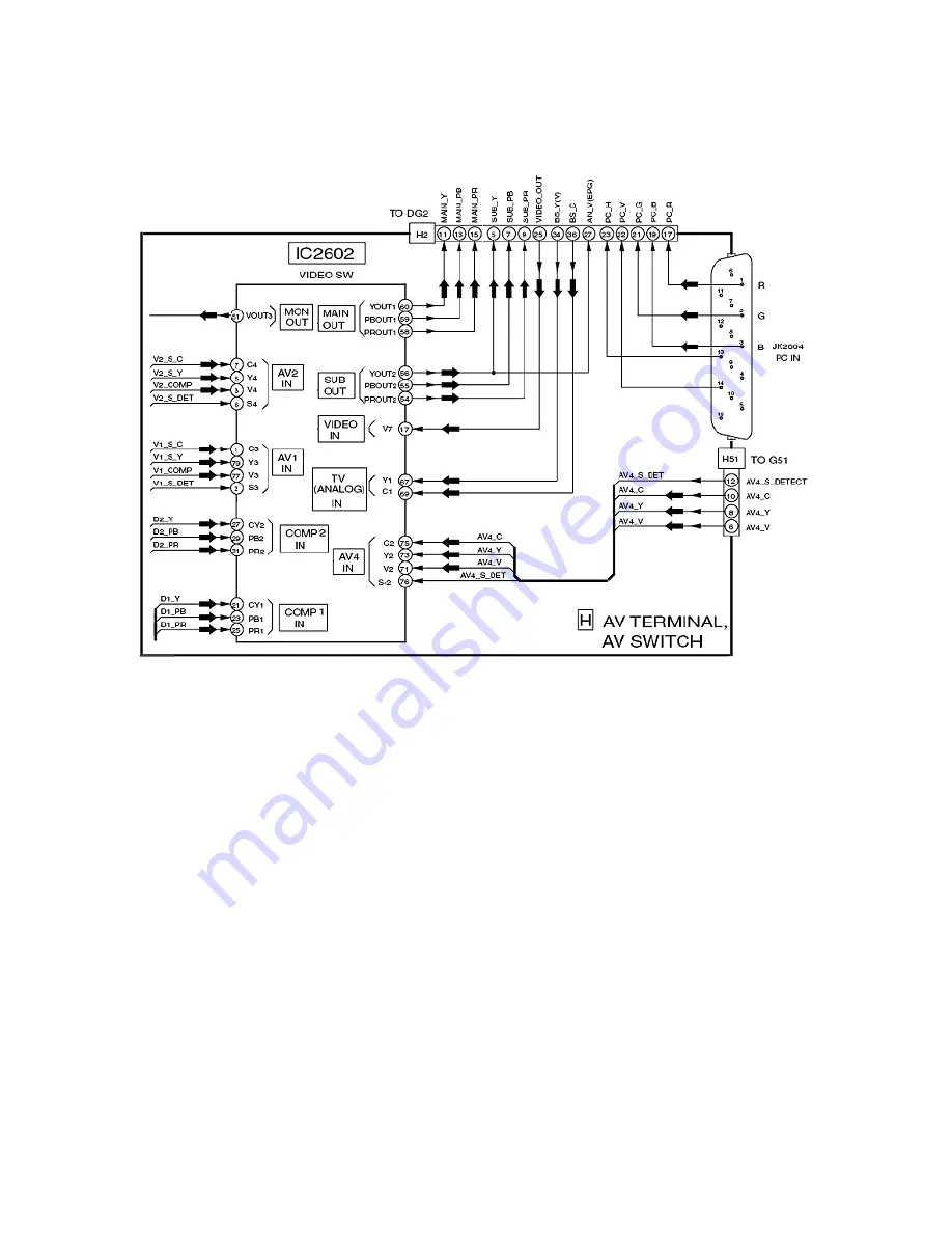
Video Input Selection Block Diagram
Figure 20
The H board contains the Video inputs 1, 2, and 3, Component Video Inputs 1 and 2,
and the Program Out jacks. All the Audio/Video input signals are applied to this board
for selection. There are two input selection ICs on this board; IC2602, which selects the
video input signals and IC2605, which selects the audio input signals. Video signals
from the digital tuner and the HDMI receiver board (DV board) pass through the DG
board and enter IC2602 of the H board via the connector H2/DG2. The selected video
signals are output to the DG Board without alteration. The output signals can be in any
of the three formats; Video, Y/C, or Y, Pb, Pr.
The PC input signal simply passes through the H board and enter the DG board via the
same connector. Selection between PC and other input signals takes place on the DG
board.
25
Summary of Contents for TH37PX50U - 37" HD PLASMA TV
Page 40: ...SC board Waveform Figure 30 SU And SD Board Shift Registers Figure 31 35 ...
Page 43: ...SS Board Schematic Figure 33 SS Board Waveform Figure 34 38 ...
Page 66: ...Adjustment Volume Locations Figure 53 61 ...
Page 67: ...Test Point Locations Figure 54 62 ...
Page 71: ...Scan and Sustain Drive Waveform Figure 55 Scan and Sustain Drive Check points Figure 56 66 ...


