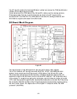
RGB Processor
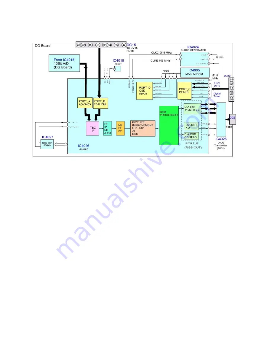
Figure 25
The digital TV and HDMI data are input directly to this integrated circuit. By avoiding
digital to analog and analog to digital conversion of those signals, the picture
information remains in its original form. As a result picture quality is pure, and
free from
noise.
The data output of IC4018 and IC4019 enters the RGB Processor, IC4026.
The RGP processor (GC4PRO) combines the selected video signals to produce Picture
in Picture. Within this integrated circuit, the 480i video signal undergoes interlace to
progressive conversion. IC4026 contains a line doubling circuit that halves the
horizontal line period of the 480i input, doubling the horizontal frequency to 31.468KHz.
IC4026 then converts the digital signal scan format from interlaced to progressive. The
signals that are of the 480P, 720P and 1080i formats simply pass through the IP
converter. The CT1/CR1/AI/DSC circuit reduces noise and improves the picture quality.
On Screen Display data such as channel numbers, Digital TV closed caption, and
picture adjustments are mixed with the video data. This circuit performs all picture
control operations such as brightness, contrast, color, tint, etc. The output signal is then
applied to the LVDS (Low Voltage Differential Signaling) transmitter for conversion into
serial data. The PEAKS firmware of the unit also resides in this IC.
The LVDS transmitter transfers the video information from the DG board to the
D board. It distributes signals with low-jitter, while creating little noise. It reduces power
consumption and the generated noise from data transmission. Another benefit of the
LVDS standard is minimal concern for cable length.
The main MCU handles all video applications. It serves as the controller that monitors
all operations of the TV section (not display) of the unit.
31
Summary of Contents for TH37PX50U - 37" HD PLASMA TV
Page 40: ...SC board Waveform Figure 30 SU And SD Board Shift Registers Figure 31 35 ...
Page 43: ...SS Board Schematic Figure 33 SS Board Waveform Figure 34 38 ...
Page 66: ...Adjustment Volume Locations Figure 53 61 ...
Page 67: ...Test Point Locations Figure 54 62 ...
Page 71: ...Scan and Sustain Drive Waveform Figure 55 Scan and Sustain Drive Check points Figure 56 66 ...


