TH-42/50PX500U
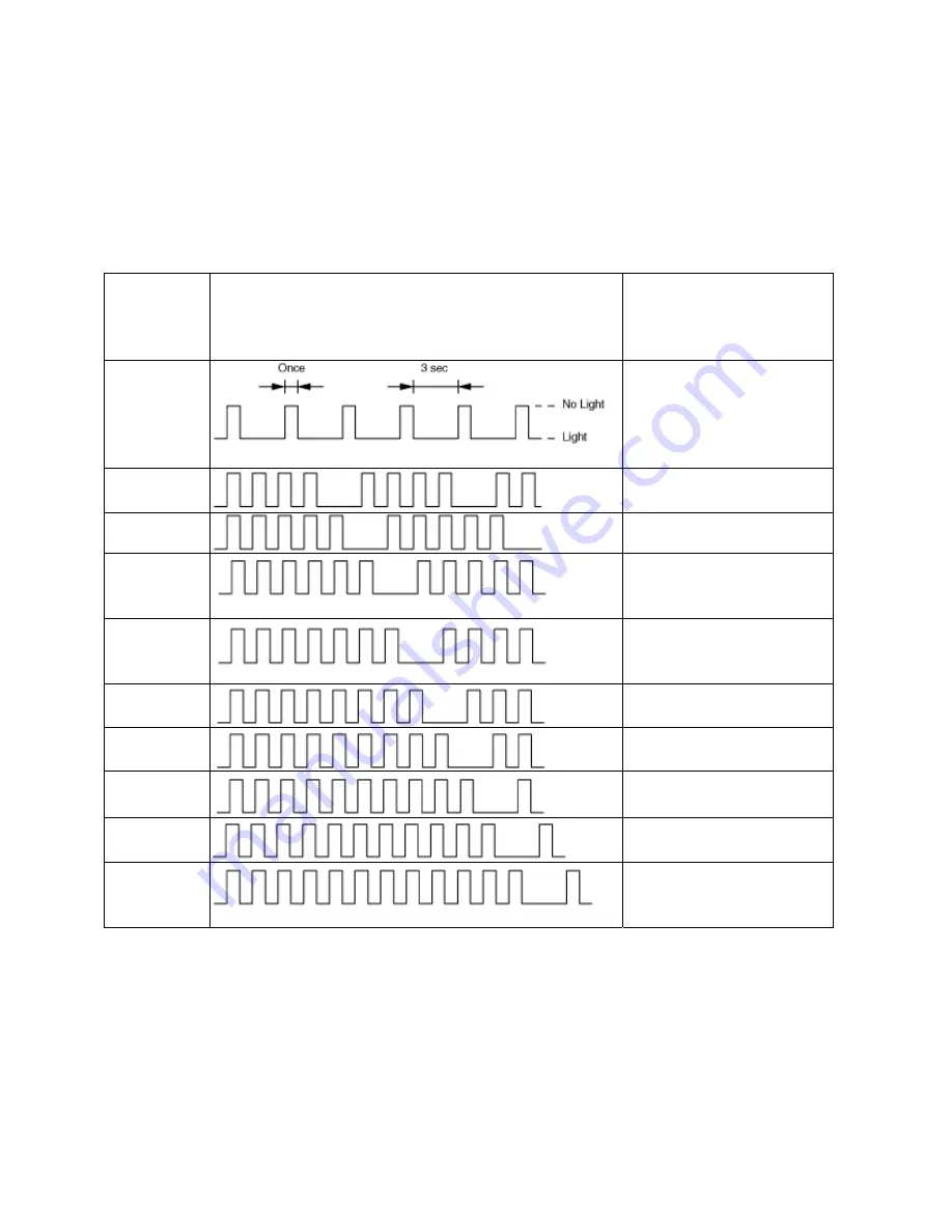
Power LED Flashing timing chart
The unit is equipped with a self-protection circuit that places it in standby when there is
an abnormality with one or more of the Power Supply circuits. The faulty circuit may be
easily identified by counting the number of flashes emitted by the power LED located in
front of the unit.
Number
of Power
LED
blinks
Blinking Timing
Suspected Board
1
D, P board
4
P, PA board (Power
SOS)
5
D, P board (5V SOS)
6
SC board (SC Energy
recovery and SC
floating voltage)
7
SS Board (SS Data
Energy recovery and
data driver)
8
SS board (SS Energy
recovery)
9
Incorrect D, DG board
10
PA Board (No power
for tuner)
11
PB board, Fan (Fan
SOS)
12
H, PB, Z Board
(Sound SOS / Speaker
shorted)
Table 4
Note:
LED indicators on the SS and SC boards alert the technician when a problem
exists. The LEDs should be lit during normal operation, a dark LED indicates that a
problem exists on that board.
40
Summary of Contents for TH37PX50U - 37" HD PLASMA TV
Page 40: ...SC board Waveform Figure 30 SU And SD Board Shift Registers Figure 31 35 ...
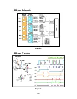
Page 43: ...SS Board Schematic Figure 33 SS Board Waveform Figure 34 38 ...
Page 66: ...Adjustment Volume Locations Figure 53 61 ...
Page 67: ...Test Point Locations Figure 54 62 ...
Page 71: ...Scan and Sustain Drive Waveform Figure 55 Scan and Sustain Drive Check points Figure 56 66 ...


