


ー 36 ー
ー 37 ー
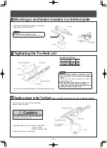
■
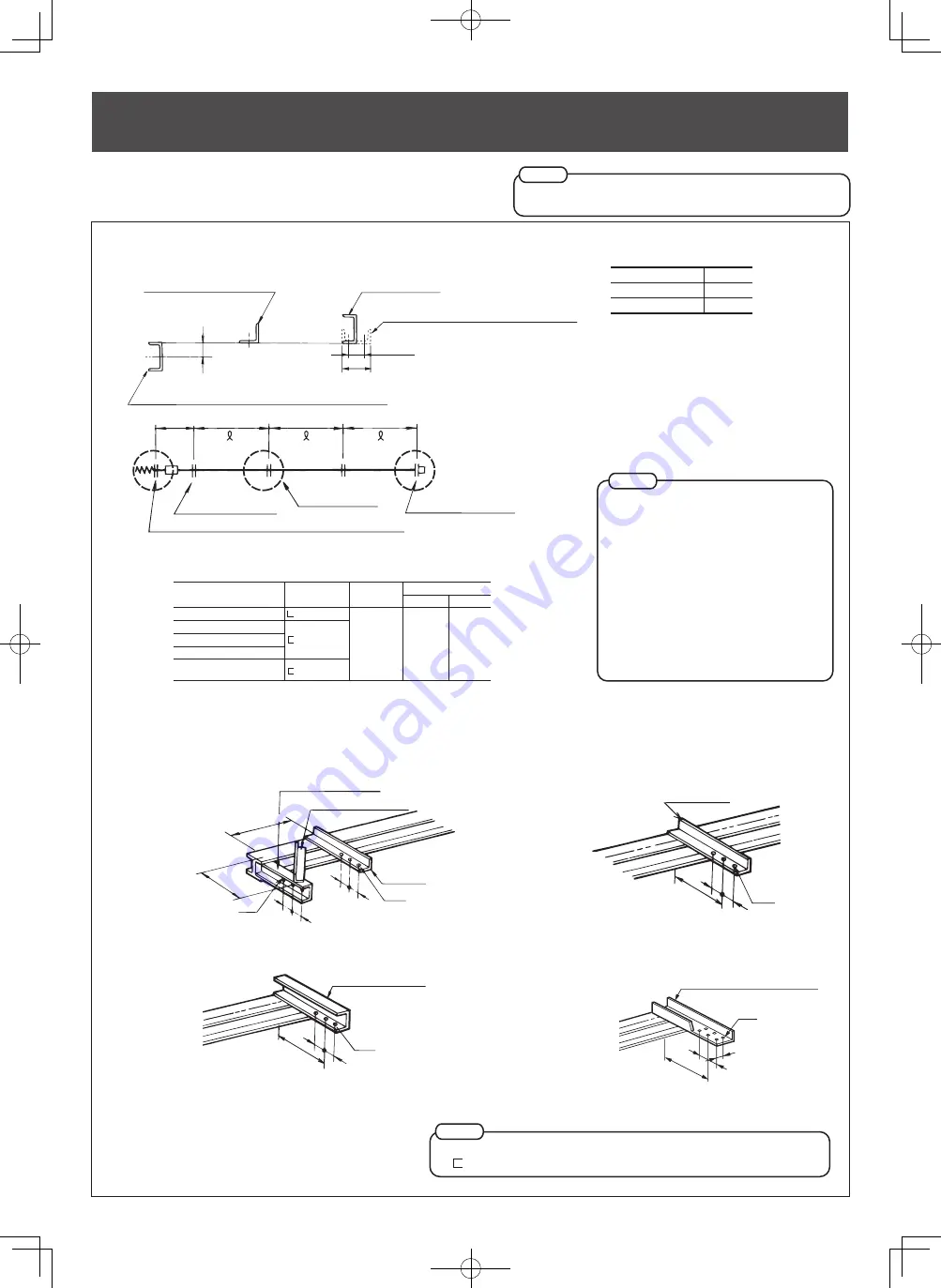
Endless line
0.5m or less
0.5m or less
0.5m or less
0.5m or less
0.5m or less
0.5m or less
0.5m or less
0.5m or less
4m or less
4m or less
4m or less
0.5m or less
0.5m or less
0.5m or less
0.5m or less
0.5m or less
0.5m or less
0.5m or less
0.5m or less
4m or less
4m or less
less than 50m
4m or less
0.5m
0.5m
Center fixed insulator
bracket (not included)
Center fixed insulator
Intermediate tension insulator
Intermediate tension insulator
Intermediate tension insulator
bracket (not included)
Center fixed insulator
bracket (not included)
Power supply
Hanger bracket
(not included)
Center feed-in
joiner
Tro-Reel unit
Intermediate tension insulator bracket (not included)
0.5m or less
0.5m or less
0.5m or less
0.5m or less
0.5m or less
0.5m or less
0.5m or less
0.5m or less
4m or less
4m or less
4m or less
4m or less 4m or less 0.5m or less
0.5m or less
0.5m or less
0.5m or less
0.5m or less
0.5m or less
0.5m or less
0.5m or less
4m or less
4m or less
0.5m
0.5m
4m or less
4m or less
50m or longer
0.5m
0.5m
Center fixed insulator
Center fixed insulator
Center fixed insulator
Intermediate tension insulator
Intermediate tension insulator
bracket (not included)
Intermediate tension insulator
bracket (not included)
Center fixed insulator
bracket (not included)
Center fixed insulator
bracket (not included)
Center fixed insulator
bracket (not included)
Power supply
Center feed-in joiner
Center fixed insulator
bracket (not supplied)
Center fixed insulator
Intermediate tension insulator
bracket (not included)
Intermediate tension insulator
Intermediate tension insulator
bracket (not included)
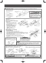
(1) Straight line of less than 50m
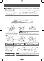
(2) Straight line of 50m or longer
Intermediate tension insulators must be positioned at 50m intervals.
●
If using a intermediate tension insulator, a center fixed insulator is also necessary.
Notes
●
If using a intermediate tension insulator, a center fixed insulator is also necessary.
Notes
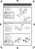
Bracket dimension and installation position
Make sure to have enough brackets for the entire length of the line.
two kinds of brackets are required: end bracket and intermediate bracket.
Since brackets are not included, it is necessary to prepare them
before installation.
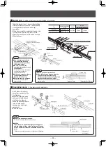
Straight installtion
Type and use of bracket
For hanger
For end tension insulator
For fixed end insulator
For fixed end insulator(with bolt)
For fixed end insulator
(In case of using hanger with an insulator)
Angle size
-40
×
40
×
5
-75
×
40
×
5
-100
×
50
×
5
A size
250
〜
300mm
B size
Minimum
Standard
75mm
100mm
End tension insulator bracket
Stay angle (for reinforcement)
Hanger
bracket
φ
14
φ
11
A
B B
B B
approx. 500m
m
①
End tension insulator section/fixed end insulator section (with bolt)
Intermediate bracket
for hanger
φ
11
B
A
B
②
Standard hanger section
Fixed end insulator bracket
φ
11
B B
A
③
Fixed end insulator section
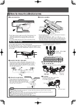
Hanger types
Standard hanger
Hanger with insulator
h
32mm
57mm
※
In the figure of bracket,
a break line is drawn to
show the work clearly.
Fixed end insulator bracket
(In case of using hanger with an insulator)
φ
11
B B
A
46
④
Fixed end insulator section
(In case of using hanger with an insulator)
Intermediate bracket for hanger
h
Fixed end insulator
bracket
End tension insulator bracket/fixed end insulator bracket (with bolt)
Intermediate bracket
for hanger
approx. 0.5m 4m or less
4m or less
46mm
100mm
4m or less
Fixed end insulator bracket
End tension insulator bracket/fixed end insulator bracket (with bolt)
Intermediate bracket
for hanger
②
③or④
①
Fixed end insulator bracket
(In case of using hanger with an insulator)
( )
( )
( )
Notes
●
If using brackets other than specified
above, use brackets of the
same or
superior strength.
Failure to do so may cause damage
due to
falling of equipment.
●
When mounting end tension insulators,
attach an intermediate
bracket 500mm
away from the end bracket.
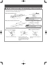
Failure to do so may cause poor collector
arm contact.
●
End brackets must be reinforced with
proper stay angles.
Failure to do so may cause damage due to
falling of equipment.
Notes
●
Mount the fixed end insulator brackets (for using a hanger with an insulator) of
-100×50×5 size in the direction as shown in the figure.
Notes


