


ー 32 ー
ー 33 ー
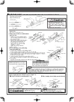
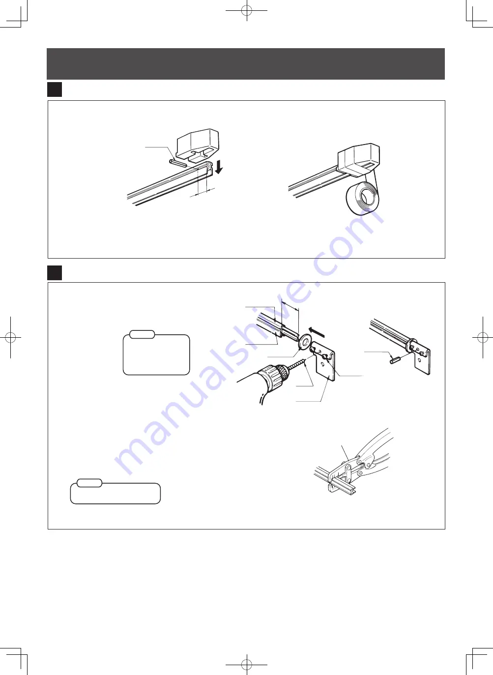
Mounting the fixed end fixture (for less than 50m)
2. Use insulation tape on the fixed insulator to prevent damage due
to falling of equipment.
1. Drill a
φ
5mm hole 20mm away from
the end of the Tro-Reel unit, drive in a
knock pin, and mount a fixed insulator.
●
When a fixed end insulator is used:
Mount the insulator the same way as
■
-
■
(Mounting
an end tension insulator).
●
When a fixed end insulator (with bolt) is used:
Knock pin
20mm
3
6
4
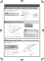
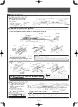
Mounting the end tension insulator terminal plate to the Tro-Reel unit
1. Cut 45mm off of the end of the Tro-Reel insulating sheath.
Attach the special washer and terminal plate. Tighten the
terminal plate screws.
2. Drill a
φ
5mm hole into the Tro-Reel conductor and drive in
a knock pin.
Insulating sheath
Tro-Reel unit
Special washer
φ
5mm
drill bit
Terminal plate
45m
m
Screw
Knock pin
4
●
Be sure to mount
the special washer.
Failure to do so may
cause damage due to
falling of equipment.
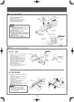
Notes
●
There is a sheath cutter for
Tro-Reel that enables smooth
cutting of insulation sheath. (For
use of 60A, 150A and 200A
units)
●
Attach insulators after the
Tro-Reel unit is mounted on the
ceiling. Attaching insulators
beforehand makes it difficult to
lift the unit.
●
The sheath cutter cannot be
used for 300A unit.
Notes
Sheath cutter
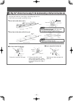
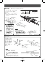
Lifting the Tro-Reel unit and securing it to the brackets starting on the fixed end insulator side
-100
×
50
×
5
Temporarily mount the unit on the hangers in order starting at the end. Pull
the unit with a rope, and make sure that it doesn
'
t sag.
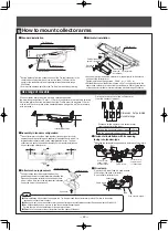
1. Remove the insulator from the hanger.
2. Fit the removed insulator into the
Tro-Reel unit and push them securely
into the hanger (as before). Failure to do
so may cause damage due to falling of
equipment.
Grip the insulator buttons with pliers and
pull it down.
●
When a fixed end insulator is used:
●
When a fixed end insulator (with bolt) is used:
■
How to mount the Tro-Reel unit
■
How to remove the Tro-Reel unit
Fixed end insulator
Mounting direction
Hanger
Tro-Reel unit
Bracket for hangers
Pull here.
Bracket for
hangers
Mounting direction
Fixed end insulator (with bolt)
Tro-Reel unit
Pull here.
46mm
Hanger with insulator
Fixed end insulator
Close together
20
75
Insulator
Special washer
Fixing piece
M10 Bolt for
hanger
Hanger
Insulator
Push here
.
Pull down.
Push here.
Hanger piece
Insulator
Tro-Reel unit
Push here
.
Push here.
5
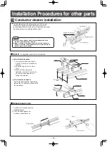
●
When using hangers with insulators, be sure to mount
two of them with close together.
Failure to do so may cause damage due to falling of
Tro-Reel unit by the damage of the hangers with insulators.
Notes
●
Be sure to mount the special washer.
Failure to do so may cause damage due to falling of equipment.
Notes
Pryor


