ー 28 ー
ー 29 ー
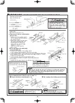
■
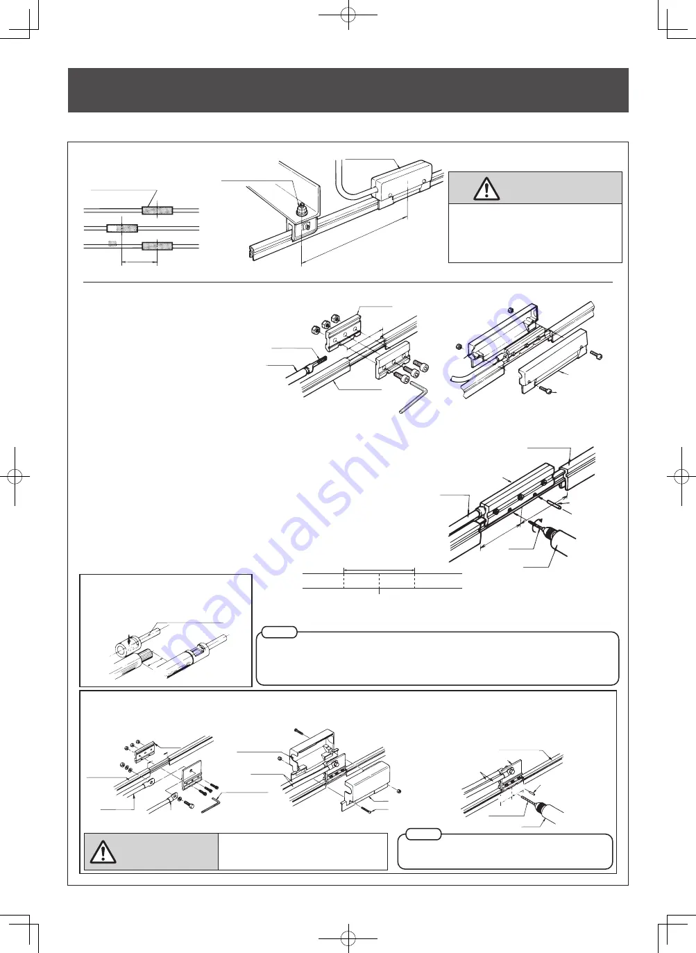
Spacer
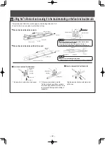
To straighten twists in the Tro-Reel unit.
■
Sheath repair cover
Insert a flat tip screwdriver between the
clip and the Tro-Reel and pry down with
the screwdriver.
●
How to remove a spacer
●
How to install a spacer
1. Loosen clip screws and align B
with the Tro-Reel unit installation
intervals.
2. Snap the clips to the Tro-Reel
units.
3. Make sure the screws are
tightened securely. Failure to do
so may cause damage due to
falling of equipment.
Clip
Screw
B
Attachment
Tro-Reel unit
Interval between
units
B
B
Screwdriver
Attachment
Tro-Reel
Clip
Nut
Cover
Cover screw
Tro-Reel unit
80mm
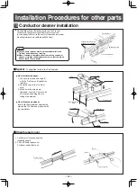
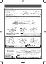
Conductor cleaner installation
●
Set the distance from the bottom surface of the Tro-reel
conductor to the center of the collector arm mount rod
(not included) to 95mm (in the center of the conductor clerner
mounting tolerance movable range 95±20mm)
Tro-Reel unit
Adjustment screw
95±20
Conductor cleaner
25×25mm
Collector arm mount rod,
25×25mm (not included)
●
The conductor cleaner must be mounted parallel to the
Tro-Reel unit without any twisting.
●
When cleaning is complete, either remove the conductor
cleaner, or tighten the adjustment screw so that the brush
doesn’t touch the conductor.
Notes
10
Installation Procedures for other parts
(Permitted movable range)
1. Cut 80mm off of each end of the
insulating sheath.
2. Fit on a Sheath repair cover .
For indoor and outdoor use.
●
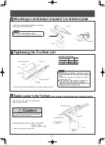
When power is to be fed from the joint of Tro-Reel units, cut 40mm off of each end of
the insulating sheath and connect them to the terminal plates. Drill a φ5mm hole in
the conductor and insert a knock pin through the hole.
Failure to do so may cause
damage due to falling of equipment.
The terminal screws must be securely tightened.
(
tightening torque 6.9
〜
7.9N
・
m
)
Failure to do so may cause fire.
●
Be sure to use a file of φ5 size.
●
The φ5mm knock pins must be securely fitted.
Failure to do so may cause damage due to falling of equipment.
■
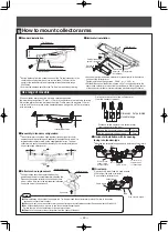
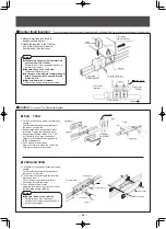
Center feed-in joiner
To feed power from an intermediate point on a line or from a joint between Tro-Reel units.
150
〜
200mm
Center feed-in joiner
200
〜
1000mm
Hanger support point
Center feed-in joiner
< 300A > (applicable wire of 150mm
2
or less, or 100mm
2
×
2)
1. Cut 80mm off of the insulating sheath.
Cut the insulating sheath completely off
the recess on the side.
2. Sandwich the conductor and the power
wire crimp-on terminal between the
terminal plates, and tighten three
screws with a hex wrench [ Setting
Torque 6.9
〜
7.9N
・
m].
Failure to do so may cause fire.
3. Fit on a cover.
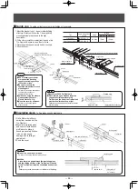
1. Cut 40mm off of each end of the insulating sheath.
Cut the insulating sheath completely off the recess on the side.
2. Sandwich the conductor and the power wire crimp-on terminal between the terminal
plates, and tighten three screws with a hex wrench [ Setting Torque 6.9
〜
7.9N
・
m].
Failure to do so may cause fire.
3. Connect the conductors with the terminal plates and drill
φ5mm boles in the conductors.Insert knock pins through the holes.
4. Fit on a cover.
Apply the insulator along the center line of the insulating sheath cutaway.
●
When power is fed from an intermediate
point on a line
■
When connecting units and feeding power simultaneously
●
When connecting units and feeding
power simultaneously
Terminal plate
Crimp-on terminal
(Accompanying)
Power wire
Tro-Reel unit
80m
m
hex wrenc
h
(not included)
Drill a knockout
hole here.
Feed-in cover
Cover screw
Tro-Reel unit
Terminal plate
Power wire
φ
5mm
drill bit
Drill
φ
5mm knock pin
40mm
40m
m
< 200A >
(applicable wire: 60-100mm
2
)
Use the special crimp-on terminal (included).
Special crimp-on terminal for 200A
Crimp here
23
〜
25mm
80mm
Making additional cuts midway makes it
easier to peel off the insulating sheath.
Terminal plate
Tro-Reel unit
Power wire
Crimp-on terminal (not included)
Terminal screw
(
M12
)
Hex key wrench
(not included)
Drill a knockout
hole here.
Power wire
Feed-in cover
Cover screw
80mm
Terminal plate
Power wire
φ
5mm knock pin
φ
5mm drill bit
Drill
40mm
40mm
Tro-Reel unit
Offsetting mounting positions
makes installation easier.
Caution
To prevent terminal screws from
loosening due to vibration, a center
feed-in joiner must be mounted 200 to
1000mm away from the hanger support
point.
Failure to do so may cause fire.
Caution
Notes
Notes
< 60A
・
150A >
(Wire units must be 50mm
2
or less)
■
When power is fed from an intermediate point on a line.


