


ー 24 ー
ー 25 ー
●
Use a tandem-type collector
arm and set the traveling
speed for switching sections
to 60m/min. or less.
●
Be sure to use only the
specified dimensions for each
mounting part.
Failure to do so may cause poor
collector arm
contact or
separation from wires.
●
In the case using at outdoors,
Please contact Pansonic
Electric Works Co.,Ltd.
●
Mount the cover by all means.
Failure to do so may cause
electric shock.
■
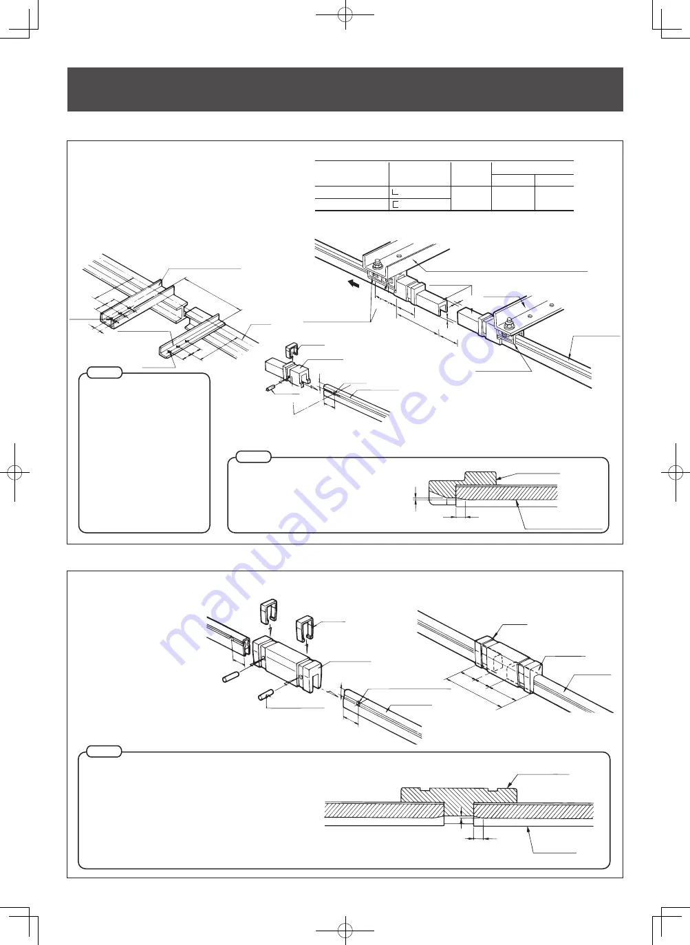
Guide cap
To guide collector arms via turntables or traversers.
■
Insulating piece
To Separate circuits electrically.
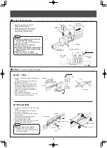
Type
Hanger bracket
Bracket for retaining tension
Angle dimensions
for 3P
-40
×
40
×
5
100
×
50
×
5
A size
250
〜
300mm
B size
Minimum
Standard
75mm
100mm
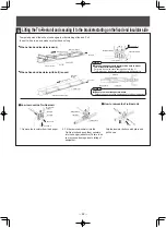
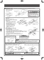
<Mounting to 300A Tro-Reel unit>
●
Since there is a gap between the guide
cap and the sliding surface to the
Tro-Reel unit, the end of the Tro-Reel unit
must be chamfered as shown right.
Failure may cause bad contact or collector
arm derailing.
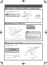
1. Mount the bracket to an
Ⅰ
-beam or other building
structure. Distances (A) from the
Ⅰ
-beam and the
mounting interval are as shown in the right
description.
2. Drill a
φ
5mm hole 20mm away from the end of
the
Tro-Reel unit.
Be sure to use a file of
φ
5 size.
3. Place the guide cap and secure it with a knock pin.
4. Fit on the cover.
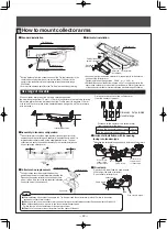
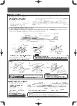
1.Drill a Φ5mm hole 20mm
away from each end of the
Tro-Reel unit
2.Mount an insulating piece
and secure it with a knock
pin.Be sure to place a
knock pin securely. Failure
to do so may cause
damage due to falling of
equipment.
3.Fit on the cover.
approx.5mm
2m
m
Sliding surface of the Tro-Reel unit
Guide cap
20mm
20m
m
7m
m
Cover
Knock pin (
φ
5
×
18mm)
φ
5mm hole (for knock pin)
Tro-Reel unit
Insulating piece
45mm
120m
m
45mm
Tro-Reel unit
Insulating piece
Cover
30mm
approx.5mm
2m
m
Insulating piece
Sliding surface of
the Tro-Reel unit
23mm
35mm
75mm
10-30mm or les
s
5mm
or less
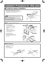
Tensio
n
Attach two standard
hangers in parallel.
Guide cap
Bracket for retaining tension (bracket used for when tensionis applied)
Hanger bracket
(bracket used when no tension is applied)
Tro-Reel unit
Standard hanger
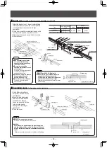
7mm or less
46mm
φ
11mm hole
46m
m
A
B
B
Hanger bracket
φ
11mm hole
A
B
B
(bracket used when no
tension is applied)
Bracket for retaining tension
(bracket used for when tension is applied)
240m
m
I-beam
Notes
●
Mount the cover by all means.
Failure to do so may cause electric shock.
●
<300A>
Since there is a gap between the insulating piece
and the sliding surface of the Tro-Reel unit, the end
of the Tro-Reel unit must be chamfered as shown at
right.
Failure may cause bad contact or collector arm derailing.
Notes
Notes
Cover
Guide Cap
φ
5mm hole
Tro-Reel unit
20mm
knock pin
(
φ
5
×
18)
7A
I-beam
●
Use a tandem-type collector
arm and set the traveling
speed for switching sections
to 60m/min. or less.
●
Be sure to use only the
specified dimensions for each
mounting part.
Failure to do so may cause poor
collector arm
contact or
separation from wires.
●
In the case using at outdoors,
Please contact Pansonic
Electric Works Co.,Ltd.
●
Mount the cover by all means.
Failure to do so may cause
electric shock.
■
Guide cap
To guide collector arms via turntables or traversers.
■
Insulating piece
To Separate circuits electrically.
Type
Hanger bracket
Bracket for retaining tension
Angle dimensions
for 3P
-40
×
40
×
5
100
×
50
×
5
A size
250
〜
300mm
B size
Minimum
Standard
75mm
100mm
<Mounting to 300A Tro-Reel unit>
●
Since there is a gap between the guide
cap and the sliding surface to the
Tro-Reel unit, the end of the Tro-Reel unit
must be chamfered as shown right.
Failure may cause bad contact or collector
arm derailing.
1. Mount the bracket to an
Ⅰ
-beam or other building
structure. Distances (A) from the
Ⅰ
-beam and the
mounting interval are as shown in the right
description.
2. Drill a
φ
5mm hole 20mm away from the end of
the
Tro-Reel unit.
Be sure to use a file of
φ
5 size.
3. Place the guide cap and secure it with a knock pin.
4. Fit on the cover.
1.Drill a Φ5mm hole 20mm
away from each end of the
Tro-Reel unit
2.Mount an insulating piece
and secure it with a knock
pin.Be sure to place a
knock pin securely. Failure
to do so may cause
damage due to falling of
equipment.
3.Fit on the cover.
approx.5mm
2m
m
Sliding surface of the Tro-Reel unit
Guide cap
20mm
20m
m
7m
m
Cover
Knock pin (
φ
5
×
18mm)
φ
5mm hole (for knock pin)
Tro-Reel unit
Insulating piece
45mm
120m
m
45mm
Tro-Reel unit
Insulating piece
Cover
30mm
approx.5mm
2m
m
Insulating piece
Sliding surface of
the Tro-Reel unit
23mm
35mm
75mm
10-30mm or les
s
5mm
or less
Tensio
n
Attach two standard
hangers in parallel.
Guide cap
Bracket for retaining tension (bracket used for when tensionis applied)
Hanger bracket
(bracket used when no tension is applied)
Tro-Reel unit
Standard hanger
7mm or less
46mm
φ
11mm hole
46m
m
A
B
B
Hanger bracket
φ
11mm hole
A
B
B
(bracket used when no
tension is applied)
Bracket for retaining tension
(bracket used for when tension is applied)
240m
m
I-beam
Notes
●
Mount the cover by all means.
Failure to do so may cause electric shock.
●
<300A>
Since there is a gap between the insulating piece
and the sliding surface of the Tro-Reel unit, the end
of the Tro-Reel unit must be chamfered as shown at
right.
Failure may cause bad contact or collector arm derailing.
Notes
Notes
Cover
Guide Cap
φ
5mm hole
Tro-Reel unit
20mm
knock pin
(
φ
5
×
18)
7A
I-beam
■絶縁ピース
回路を電気的に分割するときに使用します。
本体摺動面
2m
m
約5mm
絶縁ピース
本体摺動面
2m
m
約5mm
トロリール本体
絶縁ピース
カバー
120mm
45mm
45mm
30mm
カバー
(φ5×18)
トロリール本体
絶縁ピース
20m
m
7mm
φ5mm穴(ノックピン穴)
20mm
種 類
3 Pの場 合の
アングル方法
A寸法
B寸法
最小 標準
− 40×40×5
−100×50×5
250〜300mm 75mm 100mm
ハンガー用ブラケット
張力留めブラケット
■ガイドキャップ
ターンテーブル・トラバーサなどの乗り移り部分に使用します。
I
ビーム
φ11穴
A
B
B
φ11穴
A
B
B
( )
240
mm
46mm
張力をかけない時の
ブラケット
ハンガー用ブラケット
(張力をかける時のブラケット)
張力留めブラケット
以下
以下
張力
中間固定碍子
トロリール本体
標準ハンガー
中間固定碍子
標準ハンガーを
2コ並べます
( )
46mm
35mm
23mm
75mm
7m
m
5mm
10〜30mm以下
張力留めブラケット(張力をかける時のブラケット)
ハンガーブラケット
(張力をかけない時のブラケット)
ガイドキャップ
ご注意
●
集電アームはタンデム型を使用し乗り
移り部分の走行スピードは60m/分
以下とします。
●
各部の取り付け寸法を確実に守って
ください。
接触不良および、集電アームの脱線など
のおそれがあります。
●
屋外で使用の場合は、当社へお問い
合わせください。
●
カバーは必ずつけてください。
感電のおそれがあります。
ご注意
〈300Aの場合〉
●ガイドキャップと本体の摺動面の
段差がありますので、右図のよう
に本体端末を面取りしてください。
接触不良および、集電アームの
脱線などのおそれがあります。
ご注意
●
〈300Aの場合〉
ガイドキャップと本体の摺動面の段差がありますので、
右図のように本体端末を面取りしてください。接触不良
および、集電アームの脱線などのおそれがあります。
カバー
トロリール本体
ノックピン
(φ5×18)
φ5mm穴
20mm
7m
m
ガイドキャップ
1.トロリール本体の端末から
20mmのところにφ5mm
のノックピン穴をあける。
必ずφ5キリを使用する。
2.絶 縁 ピースを 取 り 付 け、
ノックピ ン で 固 定 す る 。
ノックピ ン は 確 実 に 取り
付ける。
落下のおそれがあります。
3.カバーをはめ込む。
1.ブラケットを
Ⅰ
ビームなどの造営材に取り付ける。
Ⅰ
ビームからの距離(A)および取付間隔は右表の通
りです。
2.本体の端末から20
mm
のところに、φ5
mm
のノッ
クピン穴をあける。必ずφ5キリを使用する。
3.ガイドキャップを取り付け、ノックピンで固定する。
4.カバーをはめる。
ノックピン
●
カバーは必ずつけてください。
感電のおそれがあります。
ガイドキャップ


