ORDER NO. PCZ06
10103CE
Service Manual
LCD TV
© 2006 Matsushita Electric Industrial Co., Ltd.
All rights reserved. Unauthorized copying and
distribution is a violation of law.
Power Source
AC 220-240V, 50Hz.
Power Consumption
Average use: 41W
Standby
condition:
1W
LCD
VGA (640 × 480 pixels)
4:3 aspect ratio LCD panel
Screen Size
408 mm(W) × 306 mm(H)
Sound
Speaker
9 cm × 5cm, 2pcs, 4Ω
Audio
Output
4W (2W + 2W), 20% THD
Headphones
M3 (3.5 mm) Jack x 1
Receiving Systems/ Band name
VHF
BAND I: CH2-CH4
BAND II: CH5-CH12
UHF
HYPER BAND :SI’-S3’, S1-S20
BAND IV, V : CH21-CH68
PAL-B/G, D/K, SECAM-L/L’, NTSC(AV input only)
Aerial-Rear
UHF/VHF
TX-20LA60F
TX-20LA60P
TX-20LA6F
TX-20LA6P
SL-131PP Chassis
Operating Conditions
Temperature: -10°C ~ 40°C
Humidity: 0%-90% RH (non-condensing)
Connection Terminals
AV1
(Scart
connecter)
21 Pin terminal (Audio/Video in, Audio/Video out, RGB in)
AV2
VIDEO
RCA
PIN
Type
×
1
S-VIDEO
Mini DIN 4-pin
AUDIO
L-R
RCA PIN Type × 2
Dimensions (W x H x D)
Including TV Stand
498mm(W) × 260mm(D) × 493mm(H)
TV
Set
Only
498mm(W) × 95mm(D) × 451mm(H)
Weight
10.9kg
Net
Note:
Design and Specifications are subject to change without notice.
Weight and Dimensions shown are approximate.
Summary of Contents for TX-20LA60P
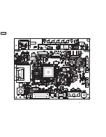
Page 15: ...15 TX 20LA6 TX 20LA60 9 Conduct Views 9 1 Foil Side ...
Page 16: ...16 TX 20LA6 TX 20LA60 ...
Page 18: ...18 TX 20LA6 TX 20LA60 ...
Page 19: ...19 TX 20LA6 TX 20LA60 10 Block and Schematic Diagrams 10 1 Schematic Diagram Notes ...
Page 20: ...20 TX 20LA6 TX 20LA60 10 2 Block Diagram ...
Page 21: ...21 TX 20LA6 TX 20LA60 10 3 Schematic Diagram ...
Page 22: ...22 TX 20LA6 TX 20LA60 ...
Page 23: ...23 TX 20LA6 TX 20LA60 ...
Page 24: ...24 TX 20LA6 TX 20LA60 ...
Page 25: ...25 TX 20LA6 TX 20LA60 ...
Page 26: ...26 TX 20LA6 TX 20LA60 ...
Page 27: ...27 TX 20LA6 TX 20LA60 Notes ...


