background image

10

TX-20LA6

TX-20LA60

  7.3. CTRL Ass’y

  1. Remove the back cover (see. 7.2.).

  2. Disconnect wires: CN2 and P504.

  3. Remove CTRL Panel Ass’y.

  4. Remove screws (2 pcs 

 ).

   5.  Remove CTRL PCB.

7.4. Power Switch Ass’y

  1. Remove the back cover (see. 7.2.).

  2. Disconnect wires: CN2 and P504.

  3. Remove CTRL Panel Ass’y.

  4. Remove screws (3 pcs 

 ).

 5. 


Remove Button CTRL Ass’y.

  6. Remove Button Power and fixing screws (2 pcs 

 ).

  7. Remove Power Switch Ass’y.

 7.5. LED Ass’y

  1. Remove the back cover (see. 7.2.).

  2. Disconnect wire: P501

  3. Remove screw (1 pcs 

 )

  4. Remove LED PCB.

 7.6. Headphone Ass’y

  1. Remove the back cover (see. 7.2.).

  2. Disconnect wire: PA09

  3. Remove screw (1 pcs 

 )

  4. Remove Headphone PCB

P501

PA09

Summary of Contents for TX-20LA60P

Page 1: ...CH2 CH4 BAND II CH5 CH12 UHF HYPER BAND SI S3 S1 S20 BAND IV V CH21 CH68 PAL B G D K SECAM L L NTSC AV input only Aerial Rear UHF VHF TX 20LA60F TX 20LA60P TX 20LA6F TX 20LA6P SL 131PP Chassis Operating Conditions Temperature 10 C 40 C Humidity 0 90 RH non condensing Connection Terminals AV1 Scart connecter 21 Pin terminal Audio Video in Audio Video out RGB in AV2 VIDEO RCA PIN Type 1 S VIDEO Mini...

Page 2: ...D ass y 10 7 6 Headphone ass y 10 7 7 Speaker left and right 11 7 8 TTL ass y 11 7 9 Power Module 11 7 10 Main ass y 11 7 11 Panel LCD 12 Page 8 Service Mode Function 13 8 1 How to enter SERVICE 13 8 2 How to exit SERVICE 13 8 3 Option Description 14 9 Conduct Views 15 9 1 Foil Side 15 9 2 Component Side 17 10 Block and Schematic Diagrams 19 10 1 Schematic Diagram Notes 19 10 2 Block Diagram 20 10...

Page 3: ...d earth ground such as a water pipe as shown in Figure 1 3 Use Leakage Current Tester Simpson 228 or equivalent to measure the potential across the measuring network 4 Check each exposed metallic part and measure the voltage at each point 5 Reserve the AC plug in the AC outlet and repeat each of the above measure 6 The potential at any point TOUGH CURRENT expressed as voltage U1 and U2 does not ex...

Page 4: ...xposure of the assembly 3 Use only a grounded tip soldering iron to solder or unsolder ES devices 4 Use only an anti static solder removal device Some solder removal devices not classified as anti static ESD protected can generate electrical charge sufficient to damage ES devices 5 Do not use freon propelled chemicals These can generate electrical charges sufficient to damage ES devices 6 Do not remo...

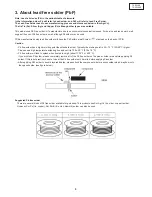
Page 5: ...on Pb free solder has a higher melting point than standard solder Typically the melting point is 50 70 F 30 40 C higher Please use a high temperature soldering iron and set it to 700 20 F 370 10 C Pb free solder will tend to splash when heated too high about 1100 F or 600 C If you must use Pb solder please completely remove all of the Pb free solder on the pins or solder area before applying Pb so...

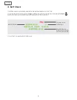
Page 6: ...he Self Check mode press the Down button on the TV set at the same time pressing the Recall button on the remote control and the screen will show when the self Check is finished Programm number Software Type When Self Check is finished you have this line within the option definition SEDNA VERSION 3 Turn off the TV to reset after SELF CHECK menu ...

Page 7: ...Y Main Board CTRL ASSY Select Switch HEADPHONE ASSY Headphone socket LED ASSY Remote Receiver LED POWER SWITCH ASSY Main power switch TTL ASSY Adapter of FFC cable POWER MODULE Power Module POWER MODULE MAIN ASSY LED ASSY CTRL ASSY HEADPHONE ASSY POWER SWITCH ASSY TTL ASSY ...

Page 8: ... B P502 P502 on Power Module connection wire 4850705N39 C P902 P905 on TTL Ass y cable FFC 4859006560 D P504 P504A connection wire 4850704S84 3 2 E P601 L SPEAKER connection wire 4850703S77 7 1 F P602 R SPEAKER connection wire 4850703S77 5 6 G P803 P801 on Power Module connection wire 4850710S32 3 4 2 H PA09 PA09B connection wire 4850705S28 1 I CN2 P500 on Power Module connection wire 4850703N47 4...

Page 9: ... so that the back cover faces upward 2 Remove the fixing screws 4pcs 3 Remove the stand ass y 7 2 Back cover 1 Remove stand ass y see 7 1 2 Remove the fixing screws 9pcs 3 Take out the Terminal Cover 4 Release the Cord Holder 5 Pull Power Cord plug throgh Back Cover hole 6 Remove Back Cover ...

Page 10: ...7 2 2 Disconnect wires CN2 and P504 3 Remove CTRL Panel Ass y 4 Remove screws 3 pcs 5 Remove Button CTRL Ass y 6 Remove Button Power and fixing screws 2 pcs 7 Remove Power Switch Ass y 7 5 LED Ass y 1 Remove the back cover see 7 2 2 Disconnect wire P501 3 Remove screw 1 pcs 4 Remove LED PCB 7 6 Headphone Ass y 1 Remove the back cover see 7 2 2 Disconnect wire PA09 3 Remove screw 1 pcs 4 Remove Head...

Page 11: ... panel 5 Unlock P905 connector clip 6 Remove FFC cable 7 9 Power Module 1 Remove the back cover see 7 2 2 Disconnect wires P500 P502 P801 3 Disconnect LCD panel wires P401 P404 P405 P408 4 Remove screws 4 pcs 5 Remove Power Module 7 10 Main Ass y 1 Remove the back cover see 7 2 2 Disconnect wires P501 P502 P504 P601 P602 P803 P902 PA09 3 Remove screws 4 pcs 4 Remove Main PCB Ass y P602 P404 PA09 P...

Page 12: ...7 2 2 Take out CTRL Panel Ass y 3 Take out TTL Ass y 4 Disconnect cables and unlock from clap wire P401 P404 P405 P408 P501 P601 P602 PA09 5 Remove screws 12 pcs 6 Take Main Frame Ass y out of Front Mask 7 Unscrew LCD Panel and Main Frame 4 screws 8 Remove LCD Panel ...

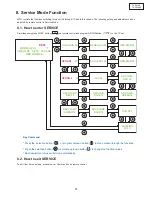
Page 13: ...3 BLUE GAIN 45 RED BIAS 32 GRN BIAS 32 AGC LEVEL 24 CCU OFF SHIPPING 4C 3C OPTION1 3C OPTION 2 4F AVL 00 ADC GAIN GREEN 18 ADC GAIN BLUE 18 ADC CLAMP RED 10 ADC CLAMP GREEN 10 ADC CLAMP BLUE 10 ADC GAIN RED 18 26 16 09 06 99 Key Command Press the selection button or program up down button to step up down through the functions Press the selection button or volume up down button to change the functi...

Page 14: ...ytes available 8 3 1 OPTION 1 B7 B6 B5 B4 B3 B2 B1 B0 1 TOP Teletext OFF FASTEXT FLOF OFF PANEL 4 3 Not used Dolby Virtual OFF PC Disable TUNER OPTIONS 00 Philips 01 Not used 10 Alps 11 Partsnic 0 TOP Teletext ON FASTEXT FLOF ON PANEL 15 9 Not used Dolby Virtual ON PC Enable 8 3 2 OPTION 2 B7 B6 B5 B4 B3 B2 B1 B0 1 Fixed to 0 PANASONIC remote control Must be set to 0 Not used Not used Full ATSS Mu...

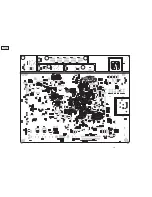
Page 15: ...15 TX 20LA6 TX 20LA60 9 Conduct Views 9 1 Foil Side ...

Page 16: ...16 TX 20LA6 TX 20LA60 ...

Page 17: ... I820 I851 IC13 F3 D3 E3 C4 E4 F4 C2 D4 D5 G5 H5 G5 H5 G3 G4 B4 G4 E2 C5 H3 G4 H4 E5 Q120 Q506 Q508 Q602 Q701 Q702 Q802 Q803 Q804 Q805 Q813 Q814 Q815 Q816 Q820 Q850 QA04 QA08 QA12 QA13 QA21 QA71 QA72 QA74 QA75 C2 B1 C3 H4 A5 B5 G3 G3 G3 H4 B5 B5 B5 B5 H3 H3 G2 G2 B2 B2 G2 C2 C2 C2 B2 X201 X501 F3 C3 FILTER SAW Z101 Z102 C3 C3 Part Location ...

Page 18: ...18 TX 20LA6 TX 20LA60 ...

Page 19: ...19 TX 20LA6 TX 20LA60 10 Block and Schematic Diagrams 10 1 Schematic Diagram Notes ...

Page 20: ...20 TX 20LA6 TX 20LA60 10 2 Block Diagram ...

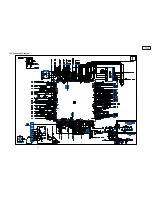
Page 21: ...21 TX 20LA6 TX 20LA60 10 3 Schematic Diagram ...

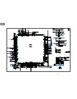
Page 22: ...22 TX 20LA6 TX 20LA60 ...

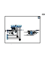
Page 23: ...23 TX 20LA6 TX 20LA60 ...

Page 24: ...24 TX 20LA6 TX 20LA60 ...

Page 25: ...25 TX 20LA6 TX 20LA60 ...

Page 26: ...26 TX 20LA6 TX 20LA60 ...

Page 27: ...27 TX 20LA6 TX 20LA60 Notes ...

Page 28: ...ote 66 TQB0E0355 MANUAL RUSSIAN BULAGLIAN ROMANIAN POLISH 1 67 TQB0E0356 MANUAL HUNGARIAN CZECH ENGLISH UKRAINIAN 1 IC s I502 X24C20LA60P IC EEPROM 32K 8 PIN DIP STIK 1 DIFFERENCES FOR MODEL TX 20LA6F Exploded View 2 485209451401 MASK FRONT 1 43 DMP4548300 S PLATE TX 20LA6F 1 see Note 66 TQB0E0357 MANUAL GERMAN DUTCH ITALIAN FRENCH SPANISH 1 67 TQB0E0358 MANUAL SWEDISH PORTUGUESE DANISH ENGLISH 1 ...

Page 29: ...159 EARPHONE ASSY DLP 20J2 EP ASSY 1 RTL 26 7178301051 SCREW TAPPTITE TT2 WAS 3X10 MFZN 3CR 1 no 25 no 18 27 4856815900 CLAMP WIRE EGI T0 4 PVC COATING 2 with screw no 28 28 7178301051 SCREW TAPPTITE TT2 WAS 3X10 MFZN 3CR 4 no 29 no 18 29 MAIN ASSY see 11 1 Different Parts List 1 RTL 30 7178301051 SCREW TAPPTITE TT2 WAS 3X10 MFZN 3CR 4 no 31 no 18 31 485AS00580 POWER LIPS IPB 6015N01 1 RTL 32 4850...

Page 30: ... WH 3CR 6 58 4857942701 RUBBER BK PHI 18X1 3T HRC 70 75 5 Ref No Part No Part Name Description Q ty Remark 59 DMP5022500 BOX PANASONIC TX 20LA6 1 60 485819D300DN PAD DOWN EPS 20J2 1 61 4858220001 BAG P E PE FOAM T0 5X800X800 1 62 485819D300UP PAD UP EPS 20J2 1 63 4858213801 BAG INSTRUCTION L D P E T0 05X250X400 1 64 486A716202 BATTERY PANASONIC AA 2 65 48BEUR7636 TRANSMITTER REMOCON EUR7636080R 1 ...

Page 31: ...QK220JBA C CHIP CERA 50V CH 22PF J 1608 1 C276 HCQK221JBA C CHIP CERA 50V CH 220PF J 1608 1 C277 HCQK221JBA C CHIP CERA 50V CH 220PF J 1608 1 C505 HCBH224KBA C CHIP CERA 25V X7R 0 22MF K 1608 1 C507 HCBH224KBA C CHIP CERA 25V X7R 0 22MF K 1608 1 C508 CEXF1E470V C ELECTRO 25V RSS 47MF 5X11 TP 1 C509 HCBH224KBA C CHIP CERA 25V X7R 0 22MF K 1608 1 C511 HCBK102KBA C CHIP CERA 50V X7R 1000PF K 1608 1 C...

Page 32: ... 50V RSS 10MF 5X11 TP 1 C815 CEXF1H479A C ELECTRO 50V RSM 4 7MF 4X7 1 C818 HCBK104KBA C CHIP CERA 50V X7R 0 1MF K 1608 1 C820 HCBK104KBA C CHIP CERA 50V X7R 0 1MF K 1608 1 C821 CEXF1C222V C ELECTRO 16V RSS 2200MF 13X25 TP 1 C822 CEXF1C102V C ELECTRO 16V RSS 1000MF 10X20 TP 1 C824 HCBK104KBA C CHIP CERA 50V X7R 0 1MF K 1608 1 C825 CEXF1C102V C ELECTRO 16V RSS 1000MF 10X20 TP 1 C826 CEXF1E471V C ELE...

Page 33: ...PEAKING 4 7UH 3 5MM K LAL02TB 1 L208 5CPZ479K02 COIL PEAKING 4 7UH 3 5MM K LAL02TB 1 L209 58C0000116 COIL BEAD HC 3550R 1 L210 5CPZ479K02 COIL PEAKING 4 7UH 3 5MM K LAL02TB 1 L213 5CPZ479K02 COIL PEAKING 4 7UH 3 5MM K LAL02TB 1 L214 5CPZ479K02 COIL PEAKING 4 7UH 3 5MM K LAL02TB 1 L505 5CPZ479K02 COIL PEAKING 4 7UH 3 5MM K LAL02TB 1 L506 5CPZ479K02 COIL PEAKING 4 7UH 3 5MM K LAL02TB 1 L507 5CPZ479K...

Page 34: ... CHIP 1 10 0 OHM 1608 1 R302 HRFT224JBA R CHIP 1 10 220K OHM J 1608 1 R303 HRFT224JBA R CHIP 1 10 220K OHM J 1608 1 R421 HRFT105JBA R CHIP 1 10 1M OHM J 1608 1 R422 HRFT103JBA R CHIP 1 10 10K OHM J 1608 1 R501 HRFT332JBA R CHIP 1 10 3 3K OHM J 1608 1 R502 HRFT332JBA R CHIP 1 10 3 3K OHM J 1608 1 R503 HRFT101JBA R CHIP 1 10 100 OHM J 1608 1 R504 HRFT152JBA R CHIP 1 10 1 5K OHM J 1608 1 R505 HRFT101...

Page 35: ...K OHM J 1608 1 R803 HRFT332JBA R CHIP 1 10 3 3K OHM J 1608 1 R804 HRFT123JBA R CHIP 1 10 12K OHM J 1608 1 R805 HRFT103JBA R CHIP 1 10 10K OHM J 1608 1 R807 HRFT103JBA R CHIP 1 10 10K OHM J 1608 1 R808 HRFT103JBA R CHIP 1 10 10K OHM J 1608 1 R809 HRFT103JBA R CHIP 1 10 10K OHM J 1608 1 R810 HRFT332JBA R CHIP 1 10 3 3K OHM J 1608 1 R811 HRFT123JBA R CHIP 1 10 12K OHM J 1608 1 R812 RD AZ473J R CARBON...

Page 36: ...10 10K OHM J 1608 1 RA96 HRFT101JBA R CHIP 1 10 100 OHM J 1608 1 RC80 HRFT000 BA R CHIP 1 10 0 OHM 1608 1 RC81 HRFT000 BA R CHIP 1 10 0 OHM 1608 1 RC82 HRFT000 BA R CHIP 1 10 0 OHM 1608 1 SW01 5S40101006 SW POWER PUSH KDC A04 10 B A1 F 1 SW701 5S50101Z90 SW TACT SKHV10910A 1 SW702 5S50101Z90 SW TACT SKHV10910A 1 SW703 5S50101Z90 SW TACT SKHV10910A 1 SW704 5S50101Z90 SW TACT SKHV10910A 1 SW705 5S50...

Reviews: