TX-20LA6
TX-20LA60
9
7. Disassembly for service
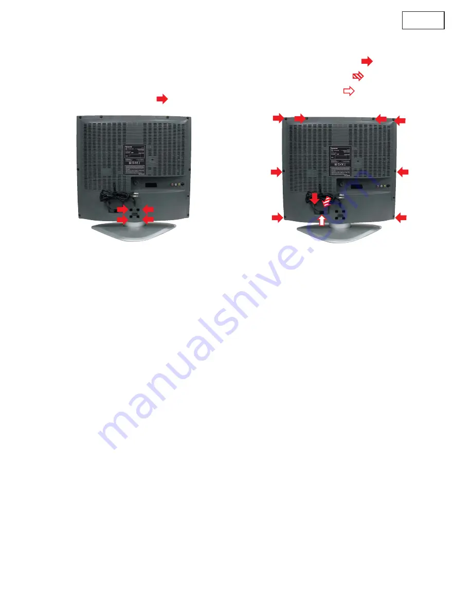
7.1 Stand Ass’y
1.
Lay down the main unit so that the back cover faces
upward.
2. Remove the fixing screws (4pcs
)
3. Remove the stand ass’y
7.2. Back cover
1. Remove stand ass’y (see 7.1.)
2. Remove the fixing screws (9pcs
)
3. Take out the Terminal Cover (
)
4. Release the Cord Holder (
)
5.
Pull Power Cord plug throgh Back Cover hole.
6. Remove Back Cover.
Summary of Contents for TX-20LA60P
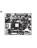
Page 15: ...15 TX 20LA6 TX 20LA60 9 Conduct Views 9 1 Foil Side ...
Page 16: ...16 TX 20LA6 TX 20LA60 ...
Page 18: ...18 TX 20LA6 TX 20LA60 ...
Page 19: ...19 TX 20LA6 TX 20LA60 10 Block and Schematic Diagrams 10 1 Schematic Diagram Notes ...
Page 20: ...20 TX 20LA6 TX 20LA60 10 2 Block Diagram ...
Page 21: ...21 TX 20LA6 TX 20LA60 10 3 Schematic Diagram ...
Page 22: ...22 TX 20LA6 TX 20LA60 ...
Page 23: ...23 TX 20LA6 TX 20LA60 ...
Page 24: ...24 TX 20LA6 TX 20LA60 ...
Page 25: ...25 TX 20LA6 TX 20LA60 ...
Page 26: ...26 TX 20LA6 TX 20LA60 ...
Page 27: ...27 TX 20LA6 TX 20LA60 Notes ...


