background image

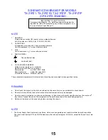
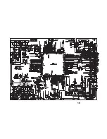
SCHEMATIC DIAGRAMS FOR MODELS

TX-21PZ1, TX-21PZ1D, TX-21PZ1F, TX-21PZ1P

(CP-521FS CHASSIS)

NOTE

1. RESISTOR

All resistors are carbon ¼W resistor, unless marked otherwise.
Unit of resistance is OHM ( ) (k=1,000, M=1,000,000)

2. CAPACITORS

All capacitors are ceramic 50V unless marked otherwise.
Unit of capacitance is  F unless otherwise stated.

3. COIL

Unit of inductance is  H, unless otherwise stated.

4. EARTH SYMBOL

Chassis Earth (Cold)

Line Earth (Hot)

5. VOLTAGE MEASUREMENT

Voltage is measured by a d.c. voltmeter.

Measurement conditions are as follows:

Power source

a.c. 220V-240V, 50Hz

Receiving Signal

Colour Bar signal (RF)

All customer controls

Maximum position

These schematic diagrams are the latest at time of printing and are subject to change without notice.

REMARKS

a. Do not touch the hot part, or the hot and cold parts at the same time, as you are liable to a shock hazard.

b. Do not short circuit the hot and cold circuits as electrical components may be damaged.
c.

Do not connect an instrument, such as an oscilloscope, to the hot and cold circuits simultaneously as this may cause

fuse failure. Connect the earth of the instruments to the earth connection of the circuit being measured.

d. Make sure to disconnect the power plug before removing the chassis.

NOTE

1. The Power Supply Circuit contains a circuit area, which uses a separate power supply to isolate the earth connection.

The circuit is defined by HOT and COLD indications in the schematic diagram. All circuits, except the Power Circuit, are 

COLD.

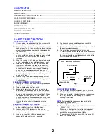
IMPORTANT SAFETY NOTICE

Components identified by

 mark have special characteristics

important for safety. When replacing any of these components, use

only manufacturers' specified parts.

1

5

Summary of Contents for TX-21PZ1

Page 1: ...EO 40 4MHz L 39 75MHz L NICAM Colour 34 47MHz PAL 34 5MHz 34 65MHz SECAM 38 3MHz 38 15MHz SECAM L Terminals AV1 IN Video 21 pin 1V p p 75 Audio 21 pin 500mV rms 10k RGB 21 pin 0 7V p p 75 AV1 OUT Video 21 pin 1V p p 75 Audio 21 pin 500mV rms 1k AV2 IN Video 21 pin 1V p p 75 Audio 21 pin 500mV rms 10k AV2 OUT Video 21 pin 1V p p 75 Audio 21 pin 500mV rms 1k AV3 FRONT Audio RCAx2 500mV rms 10k Video...

Page 2: ...n the receiver such as screw heads aerials connectors control shafts etc When the exposed metallic part has a return path to the chassis the reading should be between 4M ohm and 20M ohm When the exposed metal does not have a return path to the chassis the reading must be infinite LEAKAGE CURRENT HOT CHECK 1 Plug the a c cord directly into the a c outlet Do not use an isolation transformer for this...

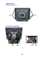
Page 3: ...3 SERVICE HINTS How to remove the rear cover 1 Remove the 5 screws as shown in Fig 2 LOCATION OF CONTROLS Fig 2 Fig 3 SCREWS SCREWS CRT Board Focus Screen MAIN Board ...

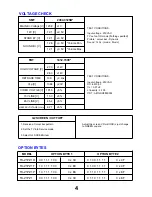
Page 4: ...C 0 x 6F 0 1 1 0 1 1 1 1 TX 21PZ1F TX 21PZ1P TX 21PZ1 SMT 2084 0125B MAIN B Voltage V 123 9 1V _ 12V V 12 1 0 5V _ STAND BY V 12 1 0 5V _ SOUND B V 12 6 0 5V _ _ Volume Min Volume Max 12 1 0 5V TEST CONDITIONS Input voltage 230VAC TV set on ON mode if othing specifed Picture colour bar Dynamic Sound 1khz mode Music FBT 1412 7009 HIGH VOLTAGE V 27 0 1kV _ _ 28 0 1kV RETRACE TIME 10 3 0 2us _ Vcp V ...

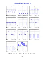
Page 5: ...WAVEFORM PATTERN TABLE 5 CONDITIONS Contrast MAX Brightness MID Colour MID Sharpness MID ...

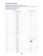
Page 6: ...ns to step up down through the functions Press buttons to alter the function values To exit Service Mode press MENU button 6 Setting in indication Note All settings are approximate Settings Special features 1 HOR CEN 35 2 SHIPPING 40 67 3 VERT SIZE 12 4 VERT CENT 45 5 S CORRECT 6 EW TRAPEZ 7 V SLOPE 32 8 V LINEAR 39 9 HOR PARAL 35 10 CORNER B 11 CORNER T 12 HOR WIDTH 13 PARABOLA 14 AVL 00 15 OPTIO...

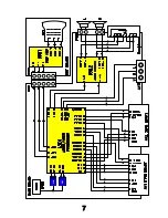
Page 7: ...7 VIDEO STEREO AUDIO BLOCK DIAGRAM Z101 Z102 ...

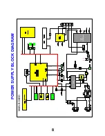
Page 8: ...LY BLOCK DIAGRAM T402 FLYBACK TRANSFORMER T401 190V 5V HEATER 5V 5V 8V S B 3 3V 5V 33V S B 3 3V S B 3 3V S B 3 3V 5V S B 5V S B 3 3V S B 3 3V S B 1 8V 1 S B 1 8V 2 12V S B 3 3V S B 1 8V 1 S B 1 8V 2 S B 5V 8V 12V 5V 131V 14V1 38V1 190V1 45V1 12V1 Q501 Q503 Q502 Q504 Q809 Q810 ...

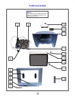
Page 9: ...PARTS LOCATION 9 NOTE The numbers on the exploded view below refer to the exploded view section of the Replacement Parts List 1 2 3 4 5 6 7 8 9 10 11 12 13 14 15 16 17 ...

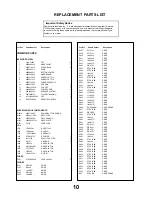
Page 10: ...4 KP1010C IC ERROR I806 DP125 IC REGULATOR I820 L7805CV IC REGULATOR I822 KIA78R08API IC REGULATOR I823 LD1117V33 IC REGULATOR I824 L7805CV IC VIDEO I901 TDA6107AJ FUSES FUSE 4A250V F801 5FSCB4022R DIODES DIODE D101 DBAT85 DIODE D102 BA282 DIODE D313 1N4937G DIODE D403 DBY228 DIODE D405 1N4937G DIODE D407 RGP15J DIODE D408 RGP15J DIODE D410 1N4004S DIODE D411 1N4004S DIODE D414 1N4004S DIODE D450 ...

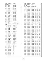
Page 11: ...5 100 Ω CARBON J50 ERD25TJ101 0 25W 5 100 Ω CARBON J76 ERD25TJ202 0 25W 5 2K Ω CARBON J83 ERD25TJ101 0 25W 5 100 Ω CARBON J84 ERD25TJ101 0 25W 5 100 Ω CARBON R103 ERD25TJ393 0 25W 5 39K Ω CARBON R104 ERD25TJ683 0 25W 5 68K Ω CARBON R105 ERD25TJ103 0 25W 5 10K Ω CARBON R106 ERD25TJ101 0 25W 5 100 Ω CARBON R107 ERD25TJ101 0 25W 5 100 Ω CARBON R114 ERD25TJ473 0 25W 5 47K Ω CARBON R115 ERD25TJ101 0 25...

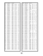
Page 12: ...0 ERD25TJ103 0 25W 5 10K Ω CARBON R611 ERD25TJ563 0 25W 5 56K Ω CARBON R612 ERD25TJ563 0 25W 5 56K Ω CARBON R650 ERD25TJ473 0 25W 5 47K Ω CARBON R660 ERD25TJ473 0 25W 5 47K Ω METAL R661 RN AZ1202F 0 17W 1 12K Ω METAL R662 RN AZ1202F 0 17W 1 12K Ω CARBON R700 ERDS1TJ232 0 5W 5 2K3 Ω CARBON R720 ERD25TJ122 0 25W 5 1K2 Ω CARBON R721 ERD25TJ181J 0 25W 5 180 Ω CARBON R722 ERD25TJ221 0 25W 5 220 Ω CARBO...

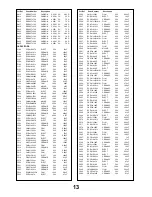
Page 13: ... 50V 2 2nF CERAMIC C522 CBXF1H104Z 50V 0 1µF CERAMIC C523 ECKC1H101J 50V 100pF FILM C524 ECQB1682JFB 100V 6 8nF ELECT C525 ECEA1H479 50V 4 7µF FILM C526 CMXL1J224J 63V 0 22µF ELECT C527 ECEA1H100 50V 10µF CERAMIC C528 ECCR1H223J 50V 22nF FILM C529 ECQV1J154JM3 63V 150nF CERAMIC C530 ECKC1H101J 50V 100pF CERAMIC C531 ECKC1H103J 50V 10nF CERAMIC C532 ECKC1H101J 50V 100pF CERAMIC C533 ECKC1H101J 50V ...

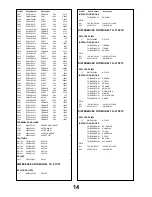
Page 14: ... CERAMIC CA04 ECKC1H101J 50V 100pF CERAMIC CA05 ECKC1H101J 50V 100pF CERAMIC CA06 ECKC1H101J 50V 100pF CERAMIC CA10 ECCR1H102J 50V 1nF CERAMIC CA28 ECKC1H101J 50V 100pF TERMINALS AND LINKS HEADPHONE SOCKET JP01 4859102130 AV TERMINAL JPA1 4859200401 AV TERMINAL JPA2 4859200401 JACK PIN BOARD JPA3 4859108450 SOCKET CRT SCT1 4859303530 SWITCHES SWITCH SW700 5S50101Z90 SWITCH SW701 5S50101Z90 SWITCH ...

Page 15: ... notice REMARKS a Do not touch the hot part or the hot and cold parts at the same time as you are liable to a shock hazard b Do not short circuit the hot and cold circuits as electrical components may be damaged c Do not connect an instrument such as an oscilloscope to the hot and cold circuits simultaneously as this may cause fuse failure Connect the earth of the instruments to the earth connecti...

Page 16: ...16 ...

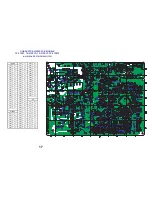
Page 17: ...02 C3 D710 E4 DA20 E3 Q807 C5 D801 D5 DA21 E3 Q809 D4 D802 D5 DA22 E3 Q810 E4 D803 D5 Q812 C6 D804 D5 Q813 D2 D805 E4 I301 B4 Q814 D3 D806 D4 I501 C2 Q815 D1 D807 D5 I502 D1 Q816 D1 D808 D4 I602 D3 D811 E4 I703 E5 D820 C5 I801 E5 D101 A1 D824 C4 I804 D4 D102 B2 D825 C6 I805 B3 D313 A4 D826 C3 I806 D4 D403 B5 D830 C4 I820 C3 D404 B5 D831 C4 I822 C4 D405 A5 D860 C4 I823 C4 D407 A5 D904 E2 I824 D4 D4...

Reviews: