background image


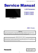
Service Manual

LCD Television


TX-24GS350 / TX-32GS350 

                                                                                               TX-32GS352 / TX-39GS352                                                
                                                                                               TX-43GS350 / TX-43GS351 
                                                                                               TX-43GS352 / TX-49GS352


                                                                                  MB211 Chassis 


©   Panasonic  Corporation 2015.


Unauthorized copying


and 

distribution is a violation of law. 

ORDER No. MQM2019_MB211_V8 


There are special components used in this equipment which are important for safety. These parts are marked       in the  
Schematic  Diagrams,  Circuit  Board  Diagrams,  Explorer  Views  and  Replacement  Parts  List.  It  is  essential  that  these 
critical  parts  should  be  replaced  with  manufacturer´s  specified  parts  to  prevent  shock,  fire  or  other  hazards.  Do  not 
modify the original design without permission of manufacturer. 

  IMPORTANT SAFETY NOTICE 

This service information is designed for experienced repair technicians only and is not designed for use by the general public. It does not 
contain warnings or cautions to advise non-technical individuals of potencial dangers in attempting to service a product. Products 
powered by electricity should be serviced or repaired only by experienced professional technicians. Any attempt to service or repair the 
product or products deal within this service information by anyone else could result in serious injury or death. 

Warning 

Summary of Contents for TX-24GS350

Page 1: ...placed with manufacturer s specified parts to prevent shock fire or other hazards Do not modify the original design without permission of manufacturer IMPORTANT SAFETY NOTICE This service information is designed for experienced repair technicians only and is not designed for use by the general public It does not contain warnings or cautions to advise non technical individuals of potencial dangers ...

Page 2: ...OSTATIC DISCHARGE ESD TO ELECTROSTATICALLY SENSITIVE ES DEVICES 3 ABOUT LEAD FREE SOLDER PBF 4 SERVICE NAVIGATION 5 SPAREPARTS IDENTIFICATION 8 SERVICE MODE FUNCTION 8 SOFTWARE UPDATE 10 HOTEL MODE 10 TROUBLESHOOTING 14 PARTS LOCATION 17 LOCATION OF LEAD WIRING 18 BLOCK DIAGRAM 23 EXPLODED VIEW 24 ...

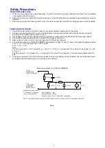
Page 3: ... point 5 Reserve the AC plug in the AC outlet and repeat each of the above measure 6 The potential at any point TOUCH CURRENT expressed as voltage U1 and U2 does not exceed the following values For a c U1 35 V peak and U2 0 35 V peak For d c U1 1 0 V Note The limit value of U2 0 35 V peak for a c and U1 1 0 V for d c correspond to the values 0 7 mA peak a c and 2 0 mA d c The limit value U1 35 V p...

Page 4: ...ted can generate electrical charge sufficient to damage ES devices 5 Do not use freon propelled chemicals These can generate electrical charges sufficient to damage ES devices 6 Do not remove a replacement ES device from its protective package until immediately before you are ready to install it Most replacement ES devices are packaged with leads electrically shorted together by conductive foam al...

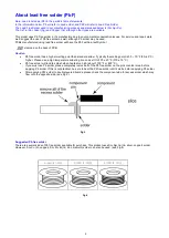
Page 5: ...as a higher melting point than standard solder Typically the melting point is 50 70 F 30 40 C higher Please use a high temperature soldering iron and set it to 700 20 F 370 10 C Pb free solder will tend to splash when heated too high about 1100 F or 600 C If you must use Pb solder please completely remove all of the Pb free solder on the pins or solder area before applying Pb solder If this is not...

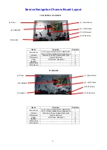
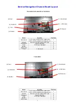
Page 6: ...n Main Board AV Terminal HDMI USB TUNER DVB A T C CI Slot Headphones Speaker out 1 P Board Main Input Power Supply Back Light 2 IR Receiver Remote Receiver 3 Panel LCD Panel Backlight 4 Speaker 5 LVDS Cable 6 2 P BOARD 4 Panel 6 LVDS Cable 5 Speaker 1 Main Board 3 IR Receiver ...

Page 7: ...VDS Cable 6 WIFI Board 7 Name Function Position Main Board AV Terminal HDMI USB TUNER DVB A T C CI Slot Headphones Speaker out 1 P Board Main Input Power Supply Back Light 2 IR Receiver Remote Receiver 3 Panel LCD Panel Backlight 4 Speaker 5 LVDS Cable 6 WIFI Board 7 TX 39GS352 TX 32GS350 TX 32GS352 3 IR Receiver 2 P BOARD 2 P BOARD 4 Panel 6 LVDS Cable 5 Speaker 4 Panel 1 Main Board 6 LVDS Cable ...

Page 8: ...er 5 LVDS Cable 6 T Con T Con Board 7 Name Function Position Main Board AV Terminal HDMI USB TUNER DVB A T C CI Slot Headphones Speaker out 1 P Board Main Input Power Supply Back Light 2 IR Receiver Remote Receiver 3 Panel LCD Panel Backlight 4 Speaker 5 LVDS Cable 6 TX 43GS350 TX 43GS351 TX 43GS352 TX 49GS352 3 IR Receiver 2 P BOARD 4 Panel 6 LVDS Cable 5 Speaker 1 Main Board 3 IR Receiver 2 P BO...

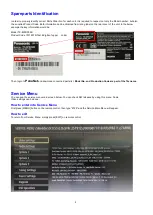
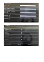
Page 9: ...el TX 43FS352B Product Code 10114979 first 8 digits of upper code Then login to PanaNet and download concerned parts list Model No and Production Code are part of the file name Service Menu You can see the service menu main screen below You can check SW releases by using this menu Some Video settings can be done How to enter into Service Menu First press MENU button on the remote control then type...

Page 10: ...9 ...

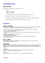
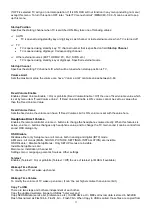
Page 11: ...is panel lock feature which does not allow the user to use the keypad touch on the TV set when it is active 5 Startup source position can be limited for the user 6 Last status could be used or not 7 Teletext could be disabled or enabled 8 NVRAM data like service list and user preferences etc could be copied or set via USB device 9 Pin8 could be used or not HOTEL TV MENU To enter hotel menu please ...

Page 12: ... the Fixed Volume Value Fixed Volume Value Sets the fixed value the volume can have If Fixed Volume Limit is ON volume is set with the value here Headphone Direct Volume Enables the remote controller volume buttons to change the headphone volume directly When this features is active volume buttons changes only headphone value and to change the TV main sound it can be control from sound OSD dialog ...

Page 13: ...ed by RETURN 1 2 3 4 shortcut Note For any MHEG supporting services sequence should be INFO RETURN 1 2 3 4 The multiple RC support is works on RC5 type of remote controllers To active this feauters the hotel mode should be active and from the hotel mode configuration menu Multiple RC support should be set as ON RC Key System Code 1 1 2 0 3 2 4 3 Welcome Message As default behavior a welcome messag...

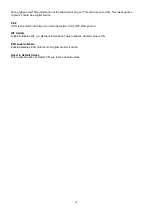
Page 14: ...vice Pin8 If ON is selected Pin8 will go on normal operation If It is OFF Pin8 ignored NIT Update Enables disables NIT i e Network Information Table updates Default value is ON EPG enable disable Enables disables EPG Electronic Program Guide function Reset to Default Values This resets all option of Hotel TV Menu to their default values ...

Page 15: ...14 TROUBLESHOOTING TV is working but there is no picture ...

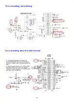
Page 16: ...15 TV is not working led is blinking CI is not working when CI module inserted ...

Page 17: ...16 USB is not working when USB inserted ...

Page 18: ... location Pos Name 1 Remote Control 2 Main power switch 3 IR Remote Receiver K Board 4a CI slot USB AV in HeadPhone HDMI 5 Speaker 6 Operation Panel 7 SPDIF SCART VGA ANT HDMI1 2 LNB 8 Stand Foot 5 7 8 3 1 4a 6 ...

Page 19: ...18 Location of Lead Wiring TX 24GS350 a Back Light n a b LVDS Cable c Speaker connection d AC Mains lead e n a f IR Remote Receiver f c b d a ...

Page 20: ...19 Location of Lead Wiring TX 32GS350 TX 32GS352 a Back Light b LVDS Cable c Speaker connection d AC Mains lead e n a f IR Remote Receiver f c b d a ...

Page 21: ...20 Location of Lead Wiring TX 39GS352B a Back Light b LVDS Cable c Speaker connection d AC Mains lead e n a f IR Remote Receiver f c b d a ...

Page 22: ...21 Location of Lead Wiring TX 43GS350 TX 43GS351 TX 43GS352 a Back Light b LVDS Cable c Speaker connection d AC Mains lead e n a f IR Remote Receiver f c b d a ...

Page 23: ...22 Location of Lead Wiring TX 49GS352 a Back Light b LVDS Cable c Speaker connection d AC Mains lead e n a f IR Remote Receiver f c b d a ...

Page 24: ...23 Block Diagram ...

Page 25: ...24 Exploded View TX 24GS350 Pos Name Qty 1 Front Cover 2 Lens 3 Screw 4 Led Board 5 Panel 6 n a 7 Speaker 8 Rear Cover 9 Rear Cover Screw 10 Stand Foot ...

Page 26: ...ploded View TX 32GS350 TX 32GS352 Pos Name Qty 1 Front Cover 2 Lens 3 IR Remote Receiver Board 4 Screw 5 Panel 6 Speaker 7 Rear Cover 8 Rear Cover Screw 9 Stand Foot 10 Foot Screw Neck 7 7 7 8 7 9 7 7 10 10 ...

Page 27: ...26 Exploded View TX 39GS352B Pos Name Qty 1 Front Cover 2 Lens 3 IR Remote Receiver Board 4 Screw 5 Panel 6 Speaker 7 Rear Cover 8 Rear Cover Screw 9 Stand Foot 10 Foot Screw Neck ...

Page 28: ...27 Exploded View TX 43GS350 TX 43GS351 TX 43GS352 Pos Name Qty 1 Front Cover 2 IR Remote Receiver Board 3 Panel 4 Speaker 5 Joystick 6 Rear Cover 7 Rear Cover Screw 8 Stand Foot 9 Foot Screw Neck ...

Page 29: ...28 Exploded View TX 49GS352 Pos Name Qty 1 Front Cover 2 IR Remote Receiver Board 3 Panel 4 Speaker 5 Joystick 6 Rear Cover 7 Rear Cover Screw 8 Stand Foot 9 Foot Screw Neck 10 n a ...

Reviews: