background image

CONTENTS

SAFETY PRECAUTIONS..........................................................................................................................................................2

SERVICE HINTS .......................................................................................................................................................................3

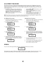
ADJUSTMENT PROCEDURE...................................................................................................................................................4

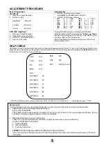
ADJUSTMENT PROCEDURE AND SELF-CHECK ..................................................................................................................5

WAVEFORM PATTERN TABLE ...............................................................................................................................................6

ALIGNMENT SETTINGS...........................................................................................................................................................7

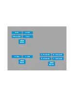
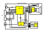
BLOCK DIAGRAMS ..................................................................................................................................................................8

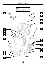
PARTS LOCATION .................................................................................................................................................................12

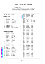
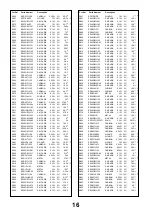
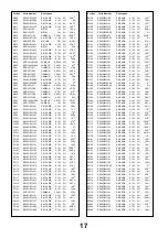
REPLACEMENT PARTS LIST ................................................................................................................................................13

SCHEMATIC DIAGRAMS .......................................................................................................................................................22

CONDUCTOR VIEWS.............................................................................................................................................................26

SAFETY PRECAUTIONS

GENERAL GUIDE LINES

1.  It is advisable to insert an isolation transformer in the

AC supply before servicing a hot chassis.

2.  When servicing, observe the original lead dress in the

high voltage circuits. If a short circuit is found, replace
all parts that have been overheated or damaged by
the short circuit.

3.  After servicing, see that all the protective devices

such as insulation barriers, insulation papers, shields
and isolation R-C combinations are correctly
installed.

4.  When the receiver is not being used for a long period

of time, unplug the power cord from the AC outlet.

5.  Potentials as high as 29,5kV {29,2kV} are present

when this receiver is in operation. Operation of the
receiver without the rear cover involves the danger of
a shock hazard from the receiver power supply.
Servicing should not be attempted by anyone who is
not familiar with the precautions necessary when
working on high voltage equipment. Always
discharge the anode of the tube.

6.  After servicing make the following leakage current

checks to prevent the customer from being exposed
to shock hazard.

LEAKAGE CURRENT COLD CHECK

1.  Unplug the AC cord and connect a jumper between

the two prongs of the plug.

2.  Turn on the receiver’s power switch.
3.  Measure the resistance value with an ohmmeter,

between the jumpered AC plug and each exposed
metallic cabinet part on the receiver, such as screw
heads, aerials, connectors, control shafts etc. When
the exposed metallic part has a return path to the
chassis, the reading should be between 4M ohm and
20M ohm. When the exposed metal does not have a
return path to the chassis, the reading must be
infinite.

LEAKAGE CURRENT HOT CHECK

1.  Plug the AC cord directly into the AC outlet. Do not

use an isolation transformer for this check.

2. Connect 

2k

 10W resistor in series with an

exposed metallic part on the receiver and an earth,
such as a water pipe.

3.  Use an AC voltmeter with high impedance to

measure the potential across the resistor.

4.  Check each exposed metallic part and check the

voltage at each point.

5.  Reverse the AC plug at the outlet and repeat each of

the above measurements.

6.  The potential at any point should not exceed

1.4 Vrms. In case a measurement is outside the limits
specified, there is a possibility of a shock hazard, and
the receiver should be repaired and rechecked before
it is returned to the customer.

X-RADIATION WARNING

1.  The potential sources of X-Radiation in TV sets are

the high voltage section and the picture tube.

2.  When using a picture tube test jig for service, ensure

that the jig is capable of handling 29,5kV without
causing X-Radiation.

NOTE: It is important to use an accurate periodically
calibrated high voltage meter.
1.  Set the brightness to minimum.
2.  Measure the high voltage. The meter should

indicate :- 28,5kV ± 1kV {28,2kV ±  1kV}.
If the meter indication is out of tolerance, immediate
service and correction is required to prevent the
possibility of premature component failure.

3.  To prevent any X-Radiation possibility, it is essential

to use the specified tube.

HOT CHECK CIRCUIT

A.C. VOLTMETER

WATER PIPE

(EARTH)

TO INSTRUMENT’S EXPOSED
METALLIC PARTS

Fig. 1.

2k

 10 Watts

2

Summary of Contents for TX-25EX4F

Page 1: ...PC to allow a number of diagnostic and control functions to be performed For more details contact your local Panasonic company BACK EXIT TX 28 25EX4F Service Manual Safety Specifications Block Diagrams Schematic Diagrams PCB Views Self Check Service Information Parts List Service Hints Disassembly Location of Controls Waveforms Mechanical View Adjustments ...

Page 2: ...BACK BACK BACK E Schematic N Schematic H Schematic Y Schematic E PCB Y PCB Audio Power supply Control Video ...

Page 3: ...00mV rms1kΩ AV1 IN Video 21 pin 1V p p 75Ω Audio 21 pin 500mV rms 10kΩ RGB 21 pin AV1 OUT Video 21 pin 1V p p 75Ω Audio 21 pin 500mV rms 1kΩ AV2 IN Video 21 pin 1V p p 75Ω Audio 21 pin 500mV rms 10kΩ S Video IN Y 1V p p 75Ω 21 pin C 0 3V p p 75Ω AV2 OUT Video 21 pin 1V p p 75Ω Audio 21 pin 500mV rms 1kΩ Selectable Output 21 pin AV3 IN Audio RCAx2 500mV rms10kΩ Video RCAx1 1V p p 75Ω High Voltage 2...

Page 4: ...abinet part on the receiver such as screw heads aerials connectors control shafts etc When the exposed metallic part has a return path to the chassis the reading should be between 4M ohm and 20M ohm When the exposed metal does not have a return path to the chassis the reading must be infinite LEAKAGE CURRENT HOT CHECK 1 Plug the AC cord directly into the AC outlet Do not use an isolation transform...

Page 5: ...SERVICE HINTS How to remove the rear cover 1 Remove the 12 screws as shown in Fig 2 LOCATION OF CONTROLS 3 SCREWS Fig 2 Fig 3 N Board E Board Y Board Focus Screen H Board ...

Page 6: ...ch the TV on 2 Go into Service Mode as explained above The screen will show 3 Press the BLUE button on the remote control The screen will show 4 Press the STR button on the TV The screen will show 5 All the tuning information stored inside the TV will now be transferred to the Memory Pack This process will take 2 3 minutes to complete and when finished the screen will show Memory Pack to TV proces...

Page 7: ...ols at the front of the set at the same time pressing the STATUS button on the remote control and the screen will show If the CCU ports have been checked and found to be incorrect or not located then will appear in place of O K Service Aids To aid in the service of our current chassis there are a number of Service Aids which have been made available LUCI interface kit Linked Utility Computer Inter...

Page 8: ...275mV 64µS 64µS 3V H Out IC601 Pin 50 Vert Out IC601 Pin 31 20mS 0 7V 13µS 3 7V SCL IC1201 Pin 3 R Out E8 Pin 5 64µS 4 6V HFLB IC601 Pin 13 64µS 6 2V R Out IC601 Pin 37 64µS 275mV G Out IC601 Pin 38 275mV 64µS Vert Drive IC451 Pin 2 20mS 57V HFLB IC701 Pin 8 64µS 1 5V G Out E8 Pin 3 64µS 4 4V SVM Out IC601 Pin 34 88mV 64µS H Out IC701 Pin 5 30mV 64µS ...

Page 9: ...al Linearity V Lin 006 Optimum setting Vertical Symmetry V Sym 002 Optimum setting DVCO DVCO 005 Receive a PAL Colour Bar Pattern For DVCO alignment press Blue button wait until the colours are changing slowly and press STR Cut off DC Cut off 0171 Ug2 Test Ug2 055 O K To adjust Cutoff connect an oscilloscope to the blue cathode adjust cutoff value using the Yellow and Blue buttons until the black ...

Page 10: ... OUT 39 Q305 Q303 Q301 E8 4 3 5 Q353 Q352 Q351 CRT 3 2 1 7 8 9 Y2 4 3 5 IC351 TUNER Q104 5HG OXH UHHQ 9LGHR Q 9 9LGHR 2XW G OUT 38 R OUT 37 G IN 46 R IN 45 Q306 Q304 Q302 Q354 7 7 VM COILS Q905 Q907 Q909 Q908 Q906 SVM OUT 34 Q950 Q951 Q3001 G 38 B 39 Y BOARD E BOARD RGB OUTPUT VIDEO PROCESSOR MICRO PROCESSOR H3 E61 E15 1 6 8 H1 1 6 8 H BOARD 8 IC3401 Q3402 8 6 3 VIDEO SWITCHING ...

Page 11: ...3 L OUT 1 R OUT 3 L OUT 2 R IN 6 L IN 2 R IN 6 L IN 47 ANA_IN1 44 MONO IN DACM_L 25 SC3_IN_R 38 SC1_IN_R 42 SC1_IN_L 41 SC2_OUT_R 27 SC2_OUT_L 28 SC2_IN_R 40 SC2_IN_L 39 Q252 Q251 2 L L 11 4 L HEADPHONE 7 R 5 L E6 1 E7 3 Q2304 Q2302 21 DACA_R 22 DACA_L E BOARD AUDIO PROCESSOR AUDIO OUTPUT AUDIO MONITOR OUT Q2303 Q2301 Q103 49 ANA_IN2 X101 X102 9 ...

Page 12: ... MATRIX 60 Q854 52 Q853 74 IC1071 Q1052 81 AV2 8 10 AV1 8 10 12 Q856 75 Q851 Q1106 Q1105 Q1107 Q1104 51 72 73 AV LINK SLOW 2 SLOW 1 SCL 1 SDA 1 59 58 Q3006 Q3007 55 VPROT KEYSCAN ON OFF R C L E D PROT 1 SLOW 2 OUT IN SLOW 1 SERVICE SCL SDA H BOARD E BOARD VIDEO SWITCHING AUDIO PROCESSOR MICRO PROCESSOR VIDEO PROCESSOR EAROM REMOTE CONTROL RECEIVER Q1051 N BOARD 8 8 D1071 10 L L L L POS NEG 82 83 P...

Page 13: ...1 P2 P1 S5 S2 S7 10 9 6 8 5 6 2 6 3 1 6 12V 200V 33V 14V 14V 27V 150V 29V 7V 15V 5V D867 Q852 Q854 Q855 1 D805 R805 R814 IC850 1 2 D862 R854 33V 16 REMOTE CONTROL RECEIVER N BOARD RESET MICRO PROCESSOR AUDIO PROCESSOR VIDEO PROCESSOR EPROM EAROM RESET REG REG REG IC3401 7 VIDEO SWITCHING EW CORRECTION POWER SUPPLY RGB OUTPUT V OUTPUT AUDIO OUTPUT D801 E BOARD Y BOARD E3 2 Y3 2 N1 2 E19 2 E1 4 1 E2...

Page 14: ...PARTS LOCATION 12 NOTE The numbers on the exploded view below refer to the mechanical section of the Replacement Parts List 19 20 16 12 14 15 4 5 7 11 3 18 13 6 17 8 1 9 2 10 ...

Page 15: ...SOR IC601 VDP3108BPPB1 HORIZONTAL OUTPUT IC701 TEA2031A POWER SUPPLY IC801 STRF6654LF51 ERROR AMPLIFER IC850 SE140N 12V REGULATOR IC851 L78M12MRB 5V REGULATOR IC852 L78M05MRB 8V REGULATOR IC853 AN78L08TA LED RECEIVER IC1071 RPM6937 V4 MICRO PROCESSOR IC1101 SDA5450C48 EPROM IC1102 27C2001 F10 DIODE IC1104 MN1381 R TA DIODE IC1105 MN1381 T TA AUDIO PROCESSOR IC2101 MSP3410DPOB4 AV SWITCHING IC3401 ...

Page 16: ... Q351 2SA1767 TRANSISTOR Q352 2SA1767 TRANSISTOR Q353 2SA1767 TRANSISTOR Q354 BC857B TRANSISTOR Q451 BC857B TRANSISTOR Q503 2SD2398 M2 TRANSISTOR Q551 BU2508AXLB TRANSISTOR Q552 2SC1473 RN TRANSISTOR Q701 BC857B TRANSISTOR Q850 2SD1273PLB TRANSISTOR Q851 BC857B TRANSISTOR Q852 2SC1383 S TRANSISTOR Q853 BC847B TRANSISTOR Q854 BC847B TRANSISTOR Q855 BC847B TRANSISTOR Q856 BC847B TRANSISTOR Q857 2SA1...

Page 17: ...M CARB JSE10 ERJ6GEY0R00 0 1W 5 0 S M CARB JA45 ERJ6GEY0R00 0 1W 5 0 S M CARB JA60 ERJ6GEY0R00 0 1W 5 0 S M CARB JA58 ERJ6GEY0R00 0 1W 5 0 S M CARB JA55 ERJ6GEY0R00 0 1W 5 0 S M CARB JA54 ERJ6GEY0R00 0 1W 5 0 S M CARB JA1 ERJ6GEY0R00 0 1W 5 0 S M CARB JA49 ERJ6GEY0R00 0 1W 5 0 S M CARB JA48 ERJ6GEY0R00 0 1W 5 0 S M CARB JA47 ERJ6GEY0R00 0 1W 5 0 S M CARB JSE12 ERJ6GEY0R00 0 1W 5 0 S M CARB JA43 ER...

Page 18: ...J6GEYJ273 0 1W 5 27K S M CARB R563 ERJ6GEYJ474 0 1W 5 470K S M CARB R564 ERJ6GEYJ623 0 1W 5 62K S M CARB R566 ERJ6GEYJ563 0 1W 5 56K WOUND R567 ERF7ZK1R0 7W 10 1 S M CARB R601 ERJ6GEYJ101 0 1W 5 100 S M CARB R602 ERJ6GEYJ821 0 1W 5 820 S M CARB R603 ERJ8GEYJ103 125W 5 10K S M CARB R604 ERJ6GEYJ101 0 1W 5 100 CARBON R605 ERD25TJ331 0 25W 5 330 CARBON R606 ERD25TJ331 0 25W 5 330 S M CARB R607 ERJ6GE...

Page 19: ...1W 5 100 S M CARB R1128 ERJ6GEYJ682 0 1W 5 6K8 S M CARB R1129 ERJ6GEYJ682 0 1W 5 6K8 S M CARB R1130 ERJ6GEYJ103 0 1W 5 10K S M CARB R1131 ERJ6GEYJ103 0 1W 5 10K S M CARB R1132 ERJ6GEYJ101 0 1W 5 100 S M CARB R1133 ERJ6GEYJ273 0 1W 5 27K S M CARB R1136 ERJ6GEYJ823 0 1W 5 82K S M CARB R1137 ERJ6GEY0R00 0 1W 5 0 S M CARB R1138 ERJ6GEYJ474 0 1W 5 470K S M CARB R1139 ERJ6GEY0R00 0 1W 5 0 S M CARB R1140...

Page 20: ...GEYJ101 0 1W 5 100 S M CARB R3606 ERJ6GEYJ101 0 1W 5 100 S M CARB R3607 ERJ6GEYJ472 0 1W 5 4K7 S M CARB R3608 ERJ6GEYJ752 0 1W 5 7K5 S M CARB R3609 ERJ6GEY0R00 0 1W 5 0 S M CARB R3610 ERJ6GEYJ102 0 1W 5 1K CAPACITORS ELECT C101 ECJ2VB1C104K 350V 100nF ELECT C102 ECJ2VB1C104K 350V 100nF ELECT C103 ECJ2VF1H104Z 350V 100nF S M CAP C104 ECUV1H102JCX 50V 1nF S M CAP C105 ECUV1H560JCX 50V 56pF S M CAP C...

Page 21: ...B 100V 470nF CERAMIC C806 ECKWNA101MBC 400V 100µF CERAMIC C807 ECKC2H472J 500V 4 7nF CERAMIC C808 ECKC2H472J 500V 4 7nF CERAMIC C809 ECKC2H472J 500V 4 7nF CERAMIC C810 ECKC2H472J 500V 4 7nF ELECT C811 ECOS2GG181NG 400V 180µF CERAMIC C814 ECKC3D102J 2KV 1nF CERAMIC C815 ECKC1H471J 50V 470pF ELECT C816 ECA1EM101GB 25V 100µF FILM C817 ECQE6104K 600V 100nF CERAMIC C818 ECKWNA332MEC 250V 3 3nF FILM C81...

Page 22: ...22JCX 50V 2 2nF S M CAP C3008 ECUV1H222JCX 50V 2 2nF S M CAP C3009 ECUV1H222JCX 50V 2 2nF ELECT C3010 ECA1CM470GB 16V 47µF S M CAP C3012 ECUV1H561JCX 50V 560pF ELECT C3013 ECJ3VB1C474K 3 5KV 470nF S M CAP C3014 ECUV1H222JCX 50V 2 2nF S M CAP C3015 ECUV1H222JCX 50V 2 2nF S M CAP C3016 ECUV1H222JCX 50V 2 2nF ELECT C3017 ECA1CM470GB 16V 47µF S M CAP C3019 ECUV1H561JCX 50V 560pF ELECT C3020 ECJ3VB1C47...

Page 23: ...ECF50X41 CABINET 15 TKY8E305 DEGAUSS COIL 16 TLK8E05140 E P C B 17 TNP8EE009AF MODEL LABEL 18 TQF8E2682 POWER CORD 19 TSX8E0027 Y P C B 20 TNP8EY012AF MISCELLANEOUS COMPONENTS OUTER CARTON TPC8E4659 TOP CUSHION TPD8E655 BOTTOM CUSHION TPD8E656 I C s EAROM IC1103 XGL2 03AF RESISTORS CARBON R357 ERDS1TJ104 0 5W 5 100K CARBON R358 ERDS1TJ104 0 5W 5 100K CARBON R359 ERDS1TJ104 0 5W 5 100K CAPACITORS C...

Page 24: ...nting and are subject to change without notice REMARKS a Do not touch the hot part or the hot and cold parts at the same time as you are liable to a shock hazard b Do not short circuit the hot and cold circuits as electrical components may be damaged c Do not connect an instrument such as an oscilloscope to the hot and cold circuits simultaneously as this may cause fuse failure Connect the earth o...

Page 25: ......

Page 26: ......

Page 27: ......

Page 28: ......

Page 29: ... Q856 F9 D865 I9 IC1104 C9 Q855 J5 D864 I10 IC1103 F8 Q854 B4 D863 G9 IC1102 D10 Q853 B4 D862 N10 IC1101 D8 Q852 B5 D861 J9 IC1051 A10 Q850 F5 D860 I10 IC852 I10 Q701 J5 D859 H5 IC851 G5 Q552 N3 D858 E5 IC850 H4 Q551 K1 D857 E5 IC801 G2 Q503 I2 D855 F4 IC701 K5 Q451 F8 D854 G4 IC601 L7 Q394 K9 D853 H3 IC451 L5 Q305 K9 D852 I4 IC251 D6 Q303 K9 D851 I4 TP S Q302 J9 D850 H4 TPE14 M5 Q301 K9 D806 G2 T...

Page 30: ...4 A7 Q353 G6 Q352 F6 Q351 F6 DIODES D906 F1 D905 G4 D904 D3 D902 G4 D901 G3 D364 C9 D363 C8 D362 B9 D361 B7 D360 D8 D359 G6 D358 E7 D357 F7 D356 G7 D355 F7 D354 G7 TEST POINTS TPY6 B8 TPY5 D5 TPY4 E5 TPY3 F6 TPY2 E7 TPY1 G6 IC S IC351 E8 26 H G F E D C B A 1 2 3 4 5 6 7 8 9 ...

Reviews: