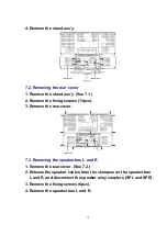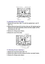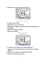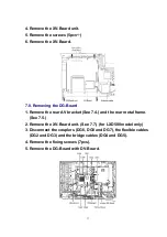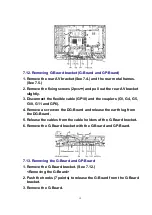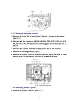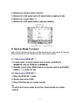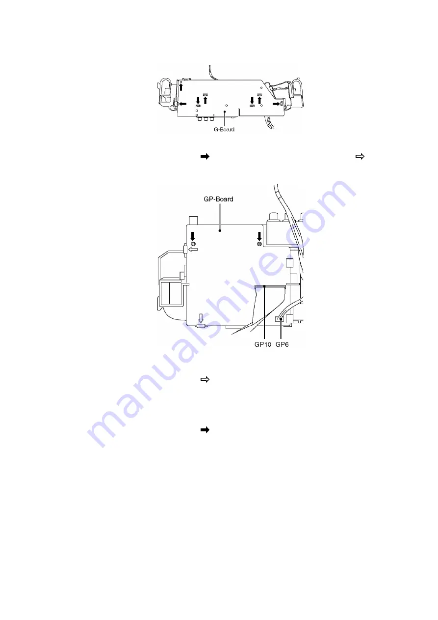
<Removing the GP-Board>
4. Remove the screws (2pcs ) and push the hooks (2 points ).
5. Remove the GP-Board.
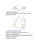
7.14. Removing the GS-Board bracket.
1. Remove the screws (3pcs ) (See figure in item 7.12.)
2. Remove the GS-Board bracket.
3. Remove the couplers (GS9 and GS10) and a flexible cable (GS3).
4. Remove the screws (2pcs ).
5. Remove the GS-Board
20
Summary of Contents for TX-26LX500F
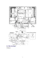
Page 12: ...6 4 Wire dressing 2 Clamping 12 ...
Page 24: ...24 ...
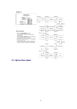
Page 25: ...8 3 Option Description 25 ...
Page 26: ...26 ...
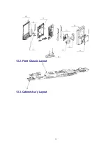
Page 32: ...13 2 Front Chassis Layout 13 3 Cabinet Ass y Layout 32 ...
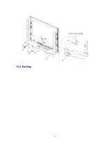
Page 33: ...13 4 Packing 33 ...
Page 58: ...IC2108 C0EBF0000354 IC 1 58 ...
Page 63: ...L8501 ELJNA2R7JB INDUCTION COIL 1 63 ...
Page 105: ...IC1104 C2CBYF000032 IC 1 105 ...
Page 107: ...IC5015 C0CBCAD00016 IC 1 107 ...
Page 111: ...Q1119 2SA207700L TRANSISTOR 1 111 ...
Page 162: ...11 Schematic Diagram 11 1 Schematic Diagram Notes 35 ...
Page 163: ...11 Schematic Diagram 11 1 Schematic Diagram Notes 35 ...

