1. Safety Precautions
1.1. General Guidelines
1. When servicing, observe the original lead dress. If a short circuit
is found, replace all parts which have been overheated or
damaged by the short circuit.
2. After servicing, see to it that all the protective devices such as
insulation barriers, insulation papers shields are properly installed.
3. After servicing, make the following leakage current checks to
prevent the customer from being exposed to shock hazards.
1.2. Touch-Current Check
1. Plug the AC cord directly into the AC outlet. Do not use an
isolation transformer for this check.
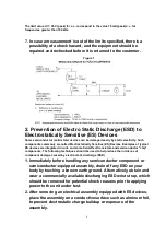
2. Connect a measuring network for touch currents between each
exposed metallic part on the set and a good earth ground such as
a water pipe, as shown in
Figure 1
.
3. Use Leakage Current Tester (Simpson 228 or equivalent) to
measure the potential across the measuring network.
4. Check each exposed metallic part, and measure the voltage at
each point.
5. Reserve the AC plug in the AC outlet and repeat each of the above
measure.
6. The potential at any point (TOUGH CURRENT) expressed as
voltage U
1
and U
2
, does not exceed the following values:
For a. c.: U
1
= 35 V (peak) and U
2
= 0.35 V (peak);
For d. c.: U
1
= 1.0 V,
Note:
The limit value of U
2
= 0.35 V (peak) for a. c. and U
1
= 1.0 V for d. c. correspond to the values 0.7
mA (peak) a. c. and 2.0 mA d. c.
3
Summary of Contents for TX-26LX500F
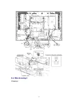
Page 12: ...6 4 Wire dressing 2 Clamping 12 ...
Page 24: ...24 ...
Page 25: ...8 3 Option Description 25 ...
Page 26: ...26 ...
Page 32: ...13 2 Front Chassis Layout 13 3 Cabinet Ass y Layout 32 ...
Page 33: ...13 4 Packing 33 ...
Page 58: ...IC2108 C0EBF0000354 IC 1 58 ...
Page 63: ...L8501 ELJNA2R7JB INDUCTION COIL 1 63 ...
Page 105: ...IC1104 C2CBYF000032 IC 1 105 ...
Page 107: ...IC5015 C0CBCAD00016 IC 1 107 ...
Page 111: ...Q1119 2SA207700L TRANSISTOR 1 111 ...
Page 162: ...11 Schematic Diagram 11 1 Schematic Diagram Notes 35 ...
Page 163: ...11 Schematic Diagram 11 1 Schematic Diagram Notes 35 ...


