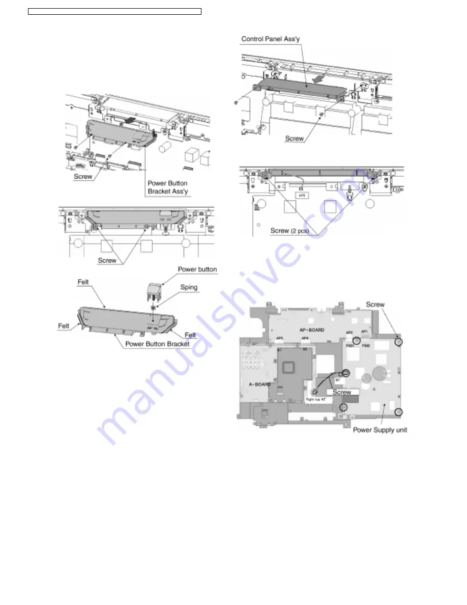
7.6. Power Button Bracket Ass’y
1. Remove the rear cover (See 7.2) and the rear support
MTG. (See 7.3)
2. Remove the fixing screws (2 pcs).
3. Remove the Power Button Bracket Ass’y.
7.7. Control Panel Ass’y
1. Remove the Power Button Bracket Ass’y. (See 7.5)
2. Remove the fixing screws (2 pcs).
3. Disconnect the coupler (AP6).
4. Remove the Control Panel Ass’y.
7.8. Power Supply unit
1. Disconnect the couplers (P301~AP2 and P302~AP1).
2. Remove the fixing screws (5 pcs).
3. Remove the Power Supply unit.
12
TX-32LX60M / TX-32LX60X / TX-32LX60A / TX-26LX60M / TX-26LX60X / TX-26LX60A
Summary of Contents for TX-26LX60A
Page 20: ...EMI Processing 32 20 TX 32LX60M TX 32LX60X TX 32LX60A TX 26LX60M TX 26LX60X TX 26LX60A ...
Page 22: ...22 TX 32LX60M TX 32LX60X TX 32LX60A TX 26LX60M TX 26LX60X TX 26LX60A ...
Page 23: ...10 3 Option Description 23 TX 32LX60M TX 32LX60X TX 32LX60A TX 26LX60M TX 26LX60X TX 26LX60A ...
Page 26: ...26 TX 32LX60M TX 32LX60X TX 32LX60A TX 26LX60M TX 26LX60X TX 26LX60A ...
Page 38: ...TX 32LX60M TX 32LX60X TX 32LX60A TX 26LX60M TX 26LX60X TX 26LX60A 38 ...
Page 54: ...32 54 TX 32LX60M TX 32LX60X TX 32LX60A TX 26LX60M TX 26LX60X TX 26LX60A ...
Page 56: ...32 56 TX 32LX60M TX 32LX60X TX 32LX60A TX 26LX60M TX 26LX60X TX 26LX60A ...


