40
AV1/2/4
AUDIO
IN
AUDIO
OUT
L
R
RGB
VIDEO
VIDEO
S-VIDEO
L
Y
P
B
P
R
R
AUDIO
RGB
VIDEO
S-VIDEO
VIDEO
COMPONENT
AV1
AV2
AV4
RGB
VIDEO
VIDEO
S-VIDEO
L
Y
P
B
P
R
Y
P
B
P
R
R
AUDIO
L
R
AUDIO
RGB
VIDEO
S-VIDEO
VIDEO
COMPONENT
COMPONENT
AV1
AV2
AV4
RGB
VIDEO
VIDEO
S-VIDEO
L
Y
P
B
P
R
R
AUDIO
RGB
VIDEO
S-VIDEO
VIDEO
COMPONENT
AV1
AV2
AV4
L
R
L
R
AUDIO
OUT
L
R
Y
P
B
P
R
Y, P
B,
P
R
OUT
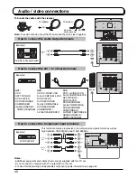
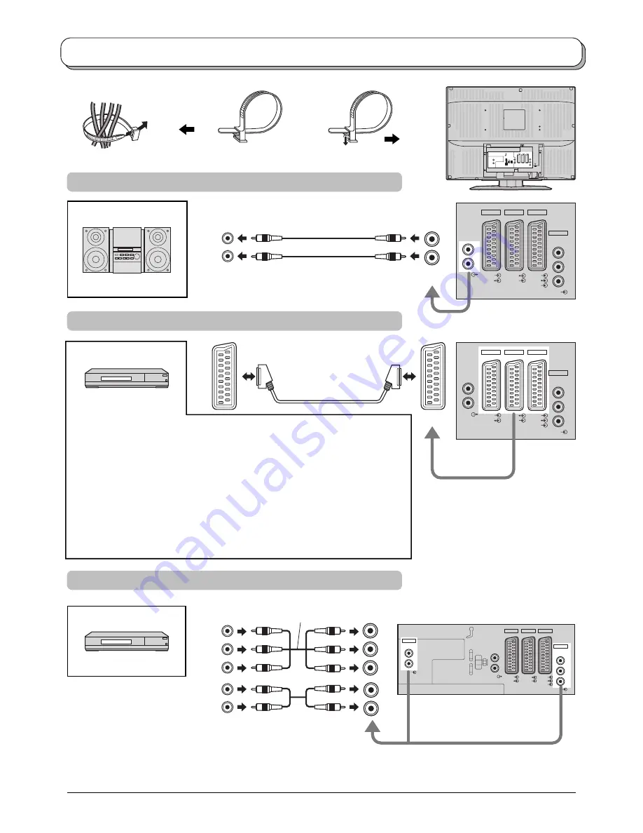
Audio / video connections
Notes:
• Additional equipment and cables shown are not supplied with this TV set.
• Do not connect a computer with TTL output (5V) to this set.
• For Scart terminal wiring and applicable component signals information see page 42.
Amplifier to Speaker System
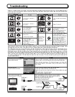
AV1:
VCR
SET TOP BOX
DVD PLAYER
DVD RECORDER
CAMCORDER
GAME CONSOLE /
COMPUTER(RGB)
DVD PLAYER
How to connect the Audio Output terminals
How to connect the AV1 / 2 / 4 Scart terminals
How to connect the Component Input terminals
This terminal accepts progressive or non-progressive signals format, as well as
high definition 750(720)/50p and 1125(1080)/50i.
AV2:
VCR / S-VIDEO VCR
Q-Link COMPATIBLE VCR
DVD PLAYER
DVD RECORDER
Q-Link COMPATIBLE
DVD RECORDER
CAMCORDER /
S-VIDEO CAMCORDER
AV4:
VCR / S-VIDEO VCR
Q-Link COMPATIBLE VCR
SET TOP BOX
DVD PLAYER
DVD RECORDER
Q-Link COMPATIBLE
DVD RECORDER
CAMCORDER /
S-VIDEO CAMCORDER
GAME CONSOLE /
COMPUTER(RGB)
To bundle the cables with the clamper
Note:
To avoid noise do not put the RF cable and the mains lead together.
To tighten:
To loosen:
Keep the
knob pressed.
Pull
Pull
Example:
Example:
Example:

