HOW TO MOVE THE CHASSIS INTO SERVICE POSITION
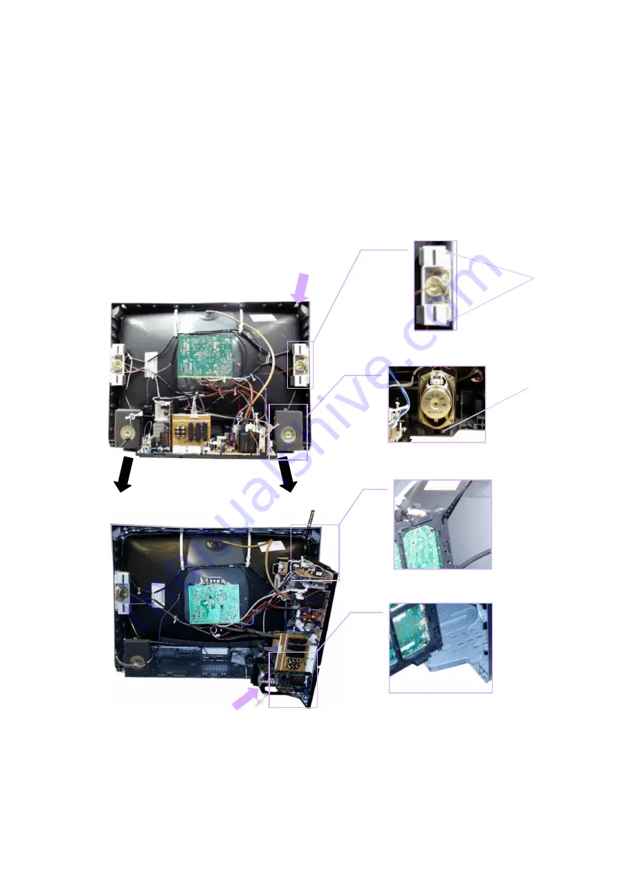
1. Remove the 3 screws (B) and (C) shown in Fig.5. / Fig.6., and remove the 2 speakers from the cabinet.
2. Affix the support strap supplied in the service pack (TZS1EK002) using a back cover screw, into the top right-hand
cabinet rib (A) shown in Fig.4.
3. Hold and lift the rear of the chassis and gently pull toward you, as shown in Fig.4.
4. Release the respective wiring clips and rotate the chassis vertically through 90°, anti-clockwise.
5. Locate the base of the chassis frame into location (D), shown in Fig.7. / Fig.9.
6. Clip the chassis frame onto the support strap, shown in Fig.7. / Fig.8.
7. After servicing replace the speakers, and ensure all wiring is returned to it’s original position before returning the recei ver
to the customer.
4
(C)
Fig.4.
Fig.6.
Fig.8.
Fig.9.
Fig.7.
(D)
(A)
Fig.5.
(B)
Summary of Contents for TX-28PB50F
Page 8: ...8 ...
Page 9: ...9 ...
Page 10: ...10 ...
Page 11: ...11 ...
Page 12: ...12 ...
Page 45: ......
Page 46: ......
Page 47: ......
Page 48: ......
Page 49: ......
Page 50: ......
Page 51: ......
Page 52: ......
Page 53: ......
Page 54: ......
Page 55: ......
Page 56: ......
Page 57: ...A BOARD TNPH0348 55 ...
Page 58: ...A BOARD TNPH0348 56 ...
Page 59: ...D DOARD TNPH0349 57 ...
Page 60: ...DF BOARD TNPA1806 ...
Page 61: ...DIODES D1011 A2 D1012 A2 D3103 B2 D3104 B2 TRANSISTORS Q1003 A2 2 1 A B G BOARD TNP8EG004 58 ...
Page 62: ...L BOARD TNPA1726 59 ...
Page 63: ...H BOARD TNPA1724 60 ...
Page 65: ...62 NOTES ...


