background image

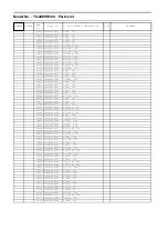
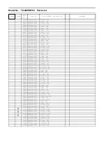
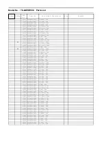
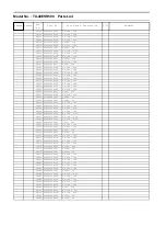
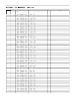
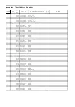
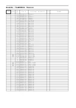
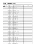
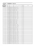
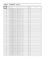
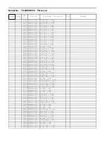
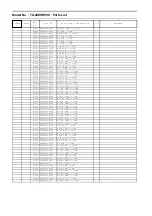
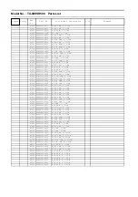
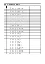
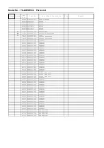
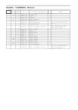
Model No. : TX-40ESR500 Parts List

Change Safety

Ref.

No.

Part No.

Part Name & Description

Q'ty

Remarks

Q7807

B1CFRL000042

TRANSISTOR

R0072

D0GAR00JA039

M 0 OHM, 1/16W

R0095

D0GAR00JA039

M 0 OHM, 1/16W

R0901

D0GA473JA039

M 47K OHM, J, 1/16W

R0912

D0GA330JA039

M 33 OHM, J, 1/16W

R0913

D0GA330JA039

M 33 OHM, J, 1/16W

R0916

D0GB332JA065

M 3.3K OHM, J, 1/10W

R0917

D0GB332JA065

M 3.3K OHM, J, 1/10W

R0918

D0GB332JA065

M 3.3K OHM, J, 1/10W

R0919

D0GB332JA065

M 3.3K OHM, J, 1/10W

R0924

D0GA360JA039

M 36 OHM, J, 1/16W

R0926

D0GA360JA039

M 36 OHM, J, 1/16W

R0927

D0GA360JA039

M 36 OHM, J, 1/16W

R0932

D0GA360JA039

M 36 OHM, J, 1/16W

R0933

D0GA360JA039

M 36 OHM, J, 1/16W

R0955

D0GA330JA039

M 33 OHM, J, 1/16W

R0956

D0GA473JA039

M 47K OHM, J, 1/16W

R0961

D0GA360JA039

M 36 OHM, J, 1/16W

R0962

D0GA360JA039

M 36 OHM, J, 1/16W

R2001

D0GA102JA039

M 1K OHM, J, 1/16W

R2004

D0GA102JA039

M 1K OHM, J, 1/16W

R2009

D0GA680JA039

M 68 OHM, J, 1/16W

R2010

D0GAR00JA039

M 0 OHM, 1/16W

R2035

D0GA223JA039

M 22K OHM, J, 1/16W

R2036

D1BA7151A023

M 7.15K OHM, F, 1/16 W

R2037

D1BA3092A023

M 30.9K OHM, F, 1/16W

R2041

D0GA103JA039

M 10K OHM, J, 1/16W

R2043

D0GA101JA039

M 100 OHM, J, 1/16W

R2044

D0GA473JA039

M 47K OHM, J, 1/16W

R2046

D0GA101JA039

M 100 OHM, J, 1/16W

R2252

D0GA183JA039

M 18K OHM, J, 1/16W

R2253

D0GA683JA039

M 68K OHM, J, 1/16W

R2254

D0GA102JA039

M 1K OHM, J, 1/16W

R2260

D0GA103JA039

M 10K OHM, J, 1/16W

R2261

D0GA473JA039

M 47K OHM, J, 1/16W

R2263

D0GA223JA039

M 22K OHM, J, 1/16W

R2264

D0GA473JA039

M 47K OHM, J, 1/16W

R2803

D0GBR00J0004

M 0 OHM, J, 1/10W

R2807

D0GBR00J0004

M 0 OHM, J, 1/10W

R2820

D0GB470JA065

M 47 OHM, J, 1/10W

R2821

D0GBR00J0004

M 0 OHM, J, 1/10W

R2823

D1BB4301A073

M 4.3K OHM, J, 1/10W

R2824

D1BB1001A073

M 1K OHM, J, 1/10W

R2852A

D1BD1911A066

M 1.91K OHM, F, 1/8W

R2853A

D1BD3091A066

M 3.09K OHM, F, 1/8W

R2854A

D1BD6041A066

M 6.04K OHM, F, 1/8W

R2855A

D1BD1692A066

M 16.9K OHM, F, 1/8W

R3101

D0GAR00JA039

M 0 OHM, 1/16W

R3162

D0GAR00JA039

M 0 OHM, 1/16W

R3163

D0GAR00JA039

M 0 OHM, 1/16W

R3164

D0GAR00JA039

M 0 OHM, 1/16W

R3166

D0GA100JA039

M 10 OHM, J, 1/16W

R3167

D1BD75R0A066

M 75 OHM, F, 1/8W

R3168

D1BD75R0A066

M 75 OHM, F, 1/8W

R3169

D1BD75R0A066

M 75 OHM, F, 1/8W

R3170

D1H81014A042

M 100 OHM, J, 1/16W

R3171

D0GAR00JA039

M 0 OHM, 1/16W

R3178

D0GA473JA039

M 47K OHM, J, 1/16W

R3185

D0GA103JA039

M 10K OHM, J, 1/16W

R3188

D0GA333JA039

M 33K OHM, J, 1/16W

R3189

D0GA333JA039

M 33K OHM, J, 1/16W

R3191

D0GA473JA039

M 47K OHM, J, 1/16W

Summary of Contents for TX-40ESR500

Page 1: ...Panasonic Corporation 2017 ORDER NO MTV1705070CE LED TV Model No TX 40ESR500 Chassis LA75 Destination CIS...

Page 2: ...etup menu 12 5 7 4 Explain the Hotel mode setup menu 12 5 8 Data Copy by USB Memory 13 5 8 1 Purpose 13 5 8 2 Preparation 13 5 8 3 Data copy from TV set to USB Memory 14 5 8 4 Data copy from USB Memor...

Page 3: ...between the jumpered AC plug and each exposed metallic cabinet part on the equipment such as screwheads connectors control shafts etc When the exposed metallic part has a return path to the chassis th...

Page 4: ...osure of the assembly 3 Use only a grounded tip soldering iron to solder or unsolder ES devices 4 Use only an anti static solder removal device Some solder removal devices not classified as anti stati...

Page 5: ...actured using lead free solder will have the PbF within a leaf Symbol PbF stamped on the back of PCB Caution Pb free solder has a higher melting point than standard solder Typically the melting point...

Page 6: ...6 3 Service Navigation 3 1 Service Hint Board Name Main Device Remarks A BOARD TUN OFDM ADV LD4 STBY EEP Repairable P BOARD Power Supply Repairable GK BOARD Function SW Repairable K BOARD LED RM CATS...

Page 7: ...mplies with CI Plus 1 ETHERNET RJ45 IEEE802 3 10BASE T 100BASE TX USB Port DC 5 V Max 500 mA Hi Speed USB USB 2 0 DIGITAL AUDIO output PCM Dolby Digital Fibre optic Receiving systems Band name DVB S S...

Page 8: ...EE times Note CS Maintenance Menu can not be entered when 3D signal input Input 2D signal to enter CS Maintenance Menu 5 1 2 Key command Press the Cursor key Up Down on the remote control to select th...

Page 9: ...or Cursor key Right on the remote control Exit Press the Exit button or the Return button on the remote control 5 4 USB HDD Drive Check 1 Select DRV CHECK in CS Maintenance Menu 2 Press OK button or C...

Page 10: ...ntrol Note for performing White balance adjustment Make a note for the setting values before changing if the settings of R GAIN B GAIN and G GAIN in WB ADJ will be changed 3 Press the cursor key Up Do...

Page 11: ...block in NAND Flash dec Peaks reboot counter System crash counter Emergency SOS counter Peaks NAND Maker ID Status4 A00027 0000015 00000 A 00027 0000015 00000 Power On period A 100hrs B 200hrs C 200h...

Page 12: ...y Initial POS Select programme number Selection Off 0 to 99 Off give priority to a last memory Initial VOL Level Adjust the volume when each time power is switched on Selection Range Off 0 to 100 Off...

Page 13: ...and then copy to other TVs 5 8 2 Preparation Make pwd file as startup file for a or b in a empty USB Memory 1 Insert a empty USB Memory to your PC 2 Right click a blank area in a USB Memory window po...

Page 14: ...a following password for a or b by using remote control a For Board replacement 2770 b For Hotel 4850 Data will be copied from TV set to USB Memory It takes around 2 to 6 minutes maximum for copying...

Page 15: ...lacement 2771 b For Hotel 4851 Data will be copied from USB Memory to TV set 4 After the completion of copying to USB Memory remove USB Memory from TV set a For Board replacement Data will be deleted...

Page 16: ...not be viewed See USB HDD Recording Produce TV reception screen and while pressing VOLUME button on the main unit press MENU button on the remote control for more than 3 seconds 6 1 2 Screen display...

Page 17: ...tch off the power with the POWER button on the main unit or the POWER button on the remote control How to confirm If the abnormal picture is displayed go into LCD Panel test mode to display the severa...

Page 18: ...sembly Instructions 7 1 Screw Removal 1 Remove screw from LCM 2 Screw back with new part screw at below diagram No Description Qty UOM Remarks 01 SCREW BTM_OMT7 7 PC 3 4 kgfcm 02 FELT T0 35 X W8 X L21...

Page 19: ...TX 40ESR500 19 7 2 Blue Tape Ornament 1 Follow Ornament specification assy in diagram below No Description Qty UOM Remarks 01 SCREW BTM_OMT7 7 PC 3 4 kgfcm 02 BLUE TAPE 0 14 MT...

Page 20: ...TX 40ESR500 20 7 3 Sticking Felt 1 Follow the diagram below for Sticking Felt No Description Qty UOM Remarks 01 FELT T0 5 X W20 X L170 2 PC 02 FELT T0 5 X W20 X L40 2 PC...

Page 21: ...se follow the sequence for assembly each part of metal No Description Qty UOM Remarks 01 CLAMPER 3 PC 02 BOTTOM BASE METAL R 1 PC 03 BOTTOM BASE METAL L 1 PC 04 BOTTOM METAL R 1 PC 05 BOTTOM METAL L 1...

Page 22: ...TX 40ESR500 22 7 5 Fixing Screw 1 Screw assy follow step below No Description Qty UOM Remarks 01 SCREW 14 PC 4 5 kgfcm 02 FELT 3 PC 03 LCD_PANEL 1 PC...

Page 23: ...TX 40ESR500 23 7 6 Cabinet Assembly 1 Follow the diagram below for Cabinet Assembly No Description Qty UOM Remarks 01 CH MOUNT BOSS 2 PC 02 GROUND SPRING 3 PC 03 SIDE_AV_BRACKET 1 PC...

Page 24: ...assy follow step below No Description Qty UOM Remarks 01 SCREW 7 PC 4 5 kgfcm 02 LED_PANEL_CASE 1 PC 03 LED_PANEL 1 PC 04 KEY_BUTTON_BRACKET 1 PC 05 SP_BRACKET_LOWER_L 1 PC 06 SP_BRACKET_LOWER_R 1 PC...

Page 25: ...TX 40ESR500 25 7 8 Speaker Assy 1 Follow the diagram below for Speaker Assy No Description Qty UOM Remarks 01 SCREW 9 PC 4 5 kgfcm 02 SP_BRACKET 2 PC 03 SPEAKER_L R 2 PC...

Page 26: ...TX 40ESR500 26 7 9 Back Cover Assy 1 1 Follow the diagram below for Back Cover Assy No Description Qty UOM Remarks 01 FELT T0 35 X W8 X L210 2 PC 02 FELT T0 9 X W5 X L15 4 PC...

Page 27: ...TX 40ESR500 27 7 10 Back Cover Assy 2 1 Follow the diagram below for Back Cover Assy No Description Qty UOM Remarks 01 FELT T0 9 X W5 X L15 2 PC...

Page 28: ...28 7 11 Back Cover Assy 3 1 Follow the diagram below for Back Cover Assy No Description Qty UOM Remarks 01 BACK_COVER 1 PC 02 VESA_METAL_BOTTOM 2 PC 03 FELT T0 35 X W10 X L75 3 PC 04 FELT T00 35 X W8...

Page 29: ...1 Follow the diagram below for Back Cover Assy No Description Qty UOM Remarks 01 MODEL NAME PLATE 1 PC 02 KEY_BUTTON_SHEET 1 PC 03 SCREW BC15 15 PC 3 5 5 5 kgfcm 04 SCREW BCSP 4 KEY1 P2 A3 9 PC 5 7 k...

Page 30: ...ever handle the module with keeping horizontal position when moving the module in order to avoid internal damage and deformation Never drop or hit the module About the work table When tightening a scr...

Page 31: ...B WiFi TP8718 5 14V 0 25V SUB3 3V TP5011 3 32V 0 165V HDMI3 3V TP4514 3 35V 0 17V SUB_AI_3 3V TP2206 3 32V 0 165V STB_1 5V TP8101 1 50V 0 07V SUB1 2V TP8100 1 20V 0 06V EU_TU_1 8V TP5704 1 84V 0 1V LN...

Page 32: ...2 0 Port 2 USB2 0 Port3 LED Information G_LED_ON R_LED_ON KEY3 KEY1 CONTROL PANEL KEY REMOCON Reciever LUMINANCE Sensor RMIN AI_SENSOR Main SW Soft Control PANEL Power DCDC PANEL_VCC_ON P12 DDR3 x16 D...

Page 33: ...agram below for Wire Dressing No Description Qty UOM Remarks 01 LVDS CABLE 1 PC 02 SPONGE T3 X W30 X L75 2 PC 03 SPONGE T3 X W25 X L30 1 PC 04 PET_TAPE 0 54 MT 60 mm X 8 05 WIRE P5 GK4 1 PC 06 WIRE A0...

Page 34: ...Model No TX 40ESR500 A Board 1 18...

Page 35: ...Model No TX 40ESR500 A Board 2 18...

Page 36: ...Model No TX 40ESR500 A Board 3 18...

Page 37: ...Model No TX 40ESR500 A Board 4 18...

Page 38: ...Model No TX 40ESR500 A Board 5 18...

Page 39: ...Model No TX 40ESR500 A Board 6 18...

Page 40: ...Model No TX 40ESR500 A Board 7 18...

Page 41: ...Model No TX 40ESR500 A Board 8 18...

Page 42: ...Model No TX 40ESR500 A Board 9 18...

Page 43: ...Model No TX 40ESR500 A Board 10 18...

Page 44: ...Model No TX 40ESR500 A Board 11 18...

Page 45: ...Model No TX 40ESR500 A Board 12 18...

Page 46: ...Model No TX 40ESR500 A Board 13 18...

Page 47: ...Model No TX 40ESR500 A Board 14 18...

Page 48: ...Model No TX 40ESR500 A Board 15 18...

Page 49: ...Model No TX 40ESR500 A Board 16 18...

Page 50: ...Model No TX 40ESR500 A Board 17 18...

Page 51: ...Model No TX 40ESR500 A Board 18 18...

Page 52: ...Model No TX 40ESR500 P Board 1 3...

Page 53: ...Model No TX 40ESR500 P Board 2 3...

Page 54: ...Model No TX 40ESR500 P Board 3 3...

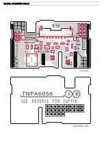
Page 55: ...Model No TX 40ESR500 K Board...

Page 56: ...Model No TX 40ESR500 GK Board...

Page 57: ...Model No TX 40ESR500 A Board Component Side...

Page 58: ...Model No TX 40ESR500 A Board Foil Side...

Page 59: ...Model No TX 40ESR500 P Board Component Side...

Page 60: ...Model No TX 40ESR500 P Board Foil Side...

Page 61: ...Model No TX 40ESR500 K Board...

Page 62: ...Model No TX 40ESR500 GK Board...

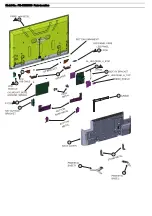
Page 63: ...Model No TX 40ESR500 Parts Location...

Page 64: ...Model No TX 40ESR500 Packing Exploded View 1...

Page 65: ...Model No TX 40ESR500 Packing Exploded View 2...

Page 66: ...807 F1J1A106A043 C 10UF 10V C2808 F1H1C104A178 C 0 1UF 16V C2851A F1J1H104A902 C 0 1UF 50V C2852A F1J1H104A902 C 0 1UF 50V C3109 F1G1H100A963 C 10PF 50V C3110 F1G1H100A963 C 10PF 50V C3111 F1G1H100A96...

Page 67: ...3 C 1UF 25V C5035 F1G1H102A830 C 1000PF 50V C5105 F1G1E103A144 C 0 01UF 25V C5140 F1G1E103A144 C 0 01UF 25V C5144 F1H1E105A153 C 1UF 25V C5202 F1K1E106A167 C 10UF 25V C5204 F1J0J2260004 C 22UF 6 3V C5...

Page 68: ...A146 C 0 1UF 16V C6745 F1G1C103A173 C 0 01UF 16V C6746 F1G1C103A173 C 0 01UF 16V C6800 F1G1H8R0A963 C 8PF 50V C6801 F1G1H8R0A963 C 8PF 50V C6803 F1G1C104A146 C 0 1UF 16V C6807 F1G1C104A146 C 0 1UF 16V...

Page 69: ...02 F2AZZ4710003 C 470UF 240V C7510 F1A3A471A079 C 470PF 1KV C7512 F2A1E4710124 C 470PF 25V C7513 F2A1E4710124 C 470PF 25V C7516 F1J1C475A225 C 4 7UF 16V C7523 F1J1H104A902 C 0 1UF 50V C7531 F1H1H104B0...

Page 70: ...F1G1C104A146 C 0 1UF 16V C8042 F1G1C104A146 C 0 1UF 16V C8043 F1G1C104A146 C 0 1UF 16V C8044 F1G1C104A146 C 0 1UF 16V C8046 F1H0J4750004 C 4 7UF 6 3V C8047 F1H0J4750004 C 4 7UF 6 3V C8049 F1H0J475000...

Page 71: ...0 F1G1C104A146 C 0 1UF 16V C8224 F1J0G2260001 C 22UF 4V C8225 F1J1A106A043 C 10UF 10V C8226 F1H0J4750004 C 4 7UF 6 3V C8227 F1G1A105A047 C 1UF 10V C8228 F1G1C104A146 C 0 1UF 16V C8229 F1G1C104A146 C 0...

Page 72: ...DIODE D5171 DZ2J180M0L DIODE D5172 DA2J10100L DIODE D5173 DZ2J062M0L DIODE D5174 B0ADCK000001 DIODE D5175 DZ2J043M0L DI0DE D5176 DA2J10100L DIODE D6800 B0JCED000012 DIODE D6801 B0JCPE000051 DIODE D68...

Page 73: ...B00004036 IC IC7201 C0DBBYY00089 IC IC7301 C0DBBYY00065 IC IC7405 B1LBZ0000070 IC IC7501 C0DBZYY00545 IC IC7800 C1ZBZ0004569 IC IC8000 C1AB00004486 IC IC8100 C0DBAYY02434 IC IC8101 C0DBAYY02531 IC IC8...

Page 74: ...INDUCTOR L8104 G1C2R2ZA0476 INDUCTOR L8701 J0JYC0000464 BEAD CORE L8702 J0JYC0000464 BEAD CORE L8706 J0JYC0000464 BEAD CORE L8900 J0JYC0000464 BEAD CORE LF7103 G0B183GA0082 LINE FILTER LF7104 G0B183GA...

Page 75: ...W R2043 D0GA101JA039 M 100 OHM J 1 16W R2044 D0GA473JA039 M 47K OHM J 1 16W R2046 D0GA101JA039 M 100 OHM J 1 16W R2252 D0GA183JA039 M 18K OHM J 1 16W R2253 D0GA683JA039 M 68K OHM J 1 16W R2254 D0GA102...

Page 76: ...A039 M 0 OHM 1 16W R4060 D0GAR00JA039 M 0 OHM 1 16W R4500 D0GA680JA039 M 68 OHM J 1 16W R4501 D0GA680JA039 M 68 OHM J 1 16W R4513 D0GA104JA039 M 100K OHM J 1 16W R4514 D0GA911JA039 M 910 OHM J 1 16W R...

Page 77: ...5150 D0GA102JA039 M 1K OHM J 1 16W R5151 D0GAR00JA039 M 0 OHM 1 16W R5154 D1BA9101A023 M 9 1K OHM F 1 16 W R5155 D1BA1242A023 M 12 4K OHM F 1 16W R5156 D0GA472JA039 M 4 7K OHM J 1 16W R5158 D0GA153JA0...

Page 78: ...OHM J 1 16W R6497 D0GA103JA039 M 10K OHM J 1 16W R6499 D0GA103JA039 M 10K OHM J 1 16W R6503 D0GAR00JA039 M 0 OHM 1 16W R6510 D0GA103JA039 M 10K OHM J 1 16W R6511 D0GA103JA039 M 10K OHM J 1 16W R6512 D...

Page 79: ...D1BD2003A066 M 200K OHM F 1 8W R7230 D1BD4422A066 M 44 2K OHM F 1 8W R7231 D1BD4303A066 M 430K OHM F 1 8W R7232 D1BD3603A066 M 360K OHM F 1 8W R7234 D1BD8203A066 M 820K OHM F 1 8W R7240 D0GF225JA048...

Page 80: ...R7823 D0GD473JA052 M 47K OHM J 1 8W R7824 D0GD183JA052 M 18K OHM J 1 8W R7825 D1BD1502A066 M 15K OHM F 1 8W R7826 D1BD1R00A066 M 1 0 OHM F 1 8W R7827 D0GD473JA052 M 47K OHM J 1 8W R7828 D0GD104JA052...

Page 81: ...00J0004 M 0 OHM J 1 10W R8809 D0GA103JA039 M 10K OHM J 1 16W R8842 D0GA473JA039 M 47K OHM J 1 16W R8843 D0GA473JA039 M 47K OHM J 1 16W R8868 D0GA103JA039 M 10K OHM J 1 16W R8871 D0GA103JA039 M 10K OHM...

Page 82: ...NAL ZA0113 K4AD01D00026 TERMINAL ZA0114 K4AD01D00026 TERMINAL ZA0115 K4AD01D00026 TERMINAL ZA0129 K4AD01D00026 TERMINAL ZA0130 K4AD01D00026 TERMINAL ZA0131 K4AD01D00026 TERMINAL ZA0132 K4AD01D00026 TE...

Page 83: ...2mm Round Screw Pedestal Assembly to TV Screw Note Screws Supplied with Stand Metal Kit Assy 9 TKP5ZA69102 SIDE_AV_BRACKET 10 TPC4GA41804 CARTON 11 TPD4GA07621 CUSHION_TOP 12 TPD4GA07631 CUSHION_BOTTO...

Reviews: