background image

CONTENTS

SAFETY PRECAUTIONS..........................................................................................................................................................2

SERVICE HINTS .......................................................................................................................................................................3

ADJUSTMENT PROCEDURE AND FACTORY SETTINGS .....................................................................................................4

WAVEFORM PATTERN TABLE ...............................................................................................................................................5

ALIGNMENT SETTINGS...........................................................................................................................................................6

BLOCK DIAGRAMS ..................................................................................................................................................................7

PARTS LOCATION .................................................................................................................................................................13

REPLACEMENT PARTS LIST ................................................................................................................................................14

SCHEMATIC DIAGRAMS .......................................................................................................................................................38

CONDUCTOR VIEWS.............................................................................................................................................................49

SAFETY PRECAUTIONS

GENERAL GUIDE LINES

1.  It is advisable to insert an isolation transformer in the

a.c. supply before servicing a hot chassis.

2.  When servicing, observe the original lead dress in the

high voltage circuits. If a short circuit is found, replace
all parts that have been overheated or damaged by
the short circuit.

3.  After servicing, see that all the protective devices

such as insulation barriers, insulation papers, shields
and isolation R-C combinations are correctly
installed.

4.  When the receiver is not being used for a long period

of time, unplug the power cord from the a.c. outlet.

5.  Potentials as high as 32.5kV are present when this

receiver is in operation. Operation of the receiver
without the rear cover involves the danger of a shock
hazard from the receiver power supply. Servicing
should not be attempted by anyone who is not
familiar with the precautions necessary when working
on high voltage equipment. Always discharge the
anode of the tube.

6.  After servicing make the following leakage current

checks to prevent the customer from being exposed
to shock hazard.

LEAKAGE CURRENT COLD CHECK

1.  Unplug the a.c. cord and connect a jumper between

the two prongs of the plug.

2.  Turn on the receiver’s power switch.
3.  Measure the resistance value with an ohmmeter,

between the jumpered a.c. plug and each exposed
metallic cabinet part on the receiver, such as screw
heads, aerials, connectors, control shafts etc. When
the exposed metallic part has a return path to the
chassis, the reading should be between 4M ohm and
20M ohm. When the exposed metal does not have a
return path to the chassis, the reading must be
infinite.

LEAKAGE CURRENT HOT CHECK

1.  Plug the a.c. cord directly into the a.c. outlet. Do not

use an isolation transformer for this check.

2. Connect 

2k

 10W resistor in series with an

exposed metallic part on the receiver and an earth,
such as a water pipe.

3.  Use an a.c. voltmeter with high impedance to

measure the potential across the resistor.

4.  Check each exposed metallic part and check the

voltage at each point.

5.  Reverse the a.c. plug at the outlet and repeat each of

the above measurements.

6.  The potential at any point should not exceed

1.4V rms. In case a measurement is outside the limits
specified, there is a possibility of a shock hazard, and
the receiver should be repaired and rechecked before
it is returned to the customer.

X-RADIATION WARNING

1.  The potential sources of X-Radiation in TV sets are

the high voltage section and the picture tube.

2.  When using a picture tube test jig for service, ensure

that the jig is capable of handling 32.5kV without
causing X-Radiation.

NOTE: It is important to use an accurate periodically
calibrated high voltage meter.

1.  Set the brightness to minimum.
2.  Measure the high voltage. The meter should indicate.

31.5kV ± 1kV.
If the meter indication is out of tolerance, immediate
service and correction is required to prevent the
possibility of premature component failure.

3.  To prevent any X-Radiation possibility, it is essential

to use the specified tube.

HOT CHECK CIRCUIT

a.c. VOLTMETER

WATER PIPE

(EARTH)

TO INSTRUMENT’S EXPOSED
METALLIC PARTS

Fig. 1.

2k

 10 Watts

2

Summary of Contents for TX-47PT10

Page 1: ...ms 1kΩ Selectable output 21 pin AV3 IN S Video IN Y 1V p p 75Ω 4 pin C 0 3V p p 75Ω Audio RCAx2 500mV rms Video RCAx1 1V p p 75Ω AV4 IN Video 21 pin 1V p p 75Ω Audio 21 pin 500mV rms 10kΩ S Video IN Y 1V p p 75Ω 21 pin C 0 3V p p 75Ω RGB 21 pin AV4 OUT Video 21 pin 1V p p 75Ω Audio 21 pin 500mV rms 1kΩ High Voltage 31 5kV 1kV Picture Tubes P16QDU11RJAS 16cm P16QDU11GHAS 16cm P16QDU11BEAS 16cm Visi...

Page 2: ... part on the receiver such as screw heads aerials connectors control shafts etc When the exposed metallic part has a return path to the chassis the reading should be between 4M ohm and 20M ohm When the exposed metal does not have a return path to the chassis the reading must be infinite LEAKAGE CURRENT HOT CHECK 1 Plug the a c cord directly into the a c outlet Do not use an isolation transformer f...

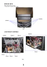
Page 3: ...VICE HINTS How to remove the rear cover 1 Remove the 11 screws as shown in Fig 2 LOCATION OF CONTROLS 3 Fig 3 P Board DG Board H Board LR Board Fig 2 SCREWS SCREWS LG Board LR Board U Board A Board D Board ...

Page 4: ...CB P2 as shown in Fig3 4 Hold and lift the rear of the chassis and gently pull the chassis towards you as shown in Fig4 5 Remove all connectors connecting away from main chassis and rotate through 90 degrees vertically as shown in Fig5 6 After servicing replace the PCB clamper A and and ensure all wiring is returned to its original position before returning the receiver to the customer WIRE DRESSI...

Page 5: ...d Adjust R Screen VR so that the voltage IK at test point TPLR1 is 165 2V G Screen VR so that the voltage IK at test point TPLG1 is 160 2V B Screen VR so that the voltage IK at test point TPLB1 is 165 2V SELF CHECK To return customer settings to factory settings and clear owner ID of all information input by the customer enter Self Check Mode To get into Self Check mode press the down v button on ...

Page 6: ... 8V Video Out IC3001 Pin 56 2 2V 64µS R Out IC1315 Pin 23 32µS 4V G Out IC1315 Pin 21 4V 32µS B Out IC1315 Pin 19 4V 32µS VFLB IC451 Pin 6 1V 20mS 32µS 4V H Drive A3 Pin 10 Vert Drive A44 Pin 24 10mS 0 9V HFLB A3 Pin 11 32µS 4V Vert Out IC451 Pin 3 10mS 88V SVM Out A44 Pin 43 1V 32µS E W Out IC501 Pin 1 32µS 8V Luminance In IC1315 Pin 37 0 9V 32µS ...

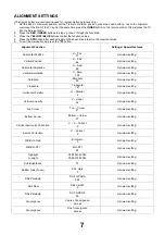
Page 7: ...Optimum setting Horizontal Amplitude H Amp 69 Optimum setting Vertical Amplitude V Amp 102 Optimum setting Parabola Parabola 30 Optimum setting Trapezoid Trapezoid 127 Optimum setting Horizontal Parallel H Parallel 8 Optimum setting Vertical Linearity V Linear 35 Optimum setting Top Corner Top Corner 21 Optimum setting Bottom Corner Bottom Corner 21 Optimum setting Vertical Symmetry Correction V S...

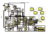
Page 8: ... IC1105 2 1 1 IC3002 12 IC2302 4 5 IC1254 8 IC1104 5 IC1109 K1 1 M11 4 A26 4 A1102 1 30 27 28 14 15 16 U2 1 30 27 28 14 15 16 A44 32 36 35 34 33 37 38 23 27 Tuner Tuner VCC D1050 VCC RM1011 A1101 20 U1 20 CVBS Switch Circuit IC1101 14 IC1106 IC1102 IC1111 32 42 53 61 69 85 106 21 87 111 116 119 123 94 1 7 13 25 38 44 37 47 5 IC1110 4 D Board L Boards A Board U Board K Board M Board 6 5V 376V 140V ...

Page 9: ...ARD L BOARDS LR LG LB U BOARD H BOARD D5 LG2 LG5 JK371 A3 D3 A2 D2 A1 D1 DY B Coil VM COIL R A4 A22 Jig R Speaker A23 L Speaker JK391 JK351 LR CRT Socket LG CRT Socket LB CRT Socket LG6 VM COIL G LG7 VM COIL B M5 RM BOARD RM1 TX 42PT10 ONLY TX 47PT10 ONLY LG4 LB1 LG3 LR1 LR2 LB2 P2 P1 P60 P BOARD D50 P50 D40 P40 D9 DY G Coil D10 DY R Coil D11 DY B Coil FOCUS PACK Mains In ONLY USED ON 47PT10 ONLY ...

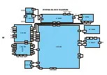
Page 10: ... V Yout 44 Yout 1 56 Cout 2 47 Cout 1 58 Y 3 17 Cin 19 Cin 20 V2 8 C4 26 Y4 24 V4 22 IC3001 IC3002 B 8 G 7 R 6 B 4 G 3 B 19 R 12 G 11 B 10 R Y 38 Y 37 B Y 39 G 21 R 23 B 13 G 14 R 15 IC1315 R 2 A Board L Board H Board 11 11 121 CVBS1A Q3006 DG Board DG01 To DG70 2 69 4 67 59 61 63 41 40 39 Q1329 Q1319 6 IC1304 84 83 Q1321 Q1322 65 Q1313 Q1312 IC1301 195 194 Q1311 205 62 Q1306 Q1327 Q1328 84 Q1308 ...

Page 11: ...6 15 17 18 12 13 10 11 H1 23 JK3406 1 3 3 3 1 1 6 2 6 2 6 2 L Out R Out L In R In R Out L Out L In R In L Out R Out L In R In AV4 AV2 AV1 R Out IC2001 60 Mono In 67 Ana In L 28 R 27 25 H P L 24 H P R 16 L 18 R IC2302 L 3 14 L R 6 11 R IC3001 R 25 L 23 R 11 R 4 L 2 R 64 L 62 L 52 L 56 R 57 L 37 R 36 R 33 L 53 R 54 L 38 R 40 A BOARD H BOARD M BOARD L R R Speaker 11 ...

Page 12: ...he numbers on the exploded view below refer to the mechanical section of the Replacement Parts List 11 33 13 17 15 14 31 24 30 29 28 32 34 3 18 7 8 9 1 20 21 22 25 26 27 2 4 5 12 16 19 23 10 PARTS LOCATION 13 ...

Page 13: ...101 INSIDE LENS PIPE TKXA02201 FOCUS VOLUME TNXB003 CARTON BOTTOM TPC8E4881 TOP CARTON TPC8E4926 PACKING CASE TPCA60901 CARTON HANDLE TPD169487 JOINT TPD169564 TOP CUSHION TPD8E749 BOTTOM CUSHION TPD8E750 TOP PAD TPD8E751 FRONT PAD TPD8E752 REAR PAD TPD8E753 TOP PAD TPD8E754 REAR PAD TPD8E755 BASE PALLET TPD8E756 PAPER PIPE TPDF0056 SUB RAIL TUAA02902 SUB RAIL TUAA08102 BATTERY PACK UM 3DJ 2P AV T...

Page 14: ...DIODE D396 MA165TA5 DIODE D397 MA165TA5 DIODE D452 MA152KTX DIODE D453 EU02AV1 DIODE D454 MA152KTX DIODE D455 MA152KTX DIODE D456 ERA22 02V3 DIODE D457 AM01ZV0 DIODE D458 AM01ZV0 DIODE D459 AM01ZV0 DIODE D460 AM01ZV0 DIODE D461 MA3030HTX DIODE D462 MA721TX DIODE D464 MA188TA5 DIODE D465 MA3039HTX DIODE D500 D1NL40V70 DIODE D501 D1NL40V70 DIODE D502 MA4150TA DIODE D503 FMV 3GULF730 DIODE D504 MA427...

Page 15: ...R Q462 BC847B TRANSISTOR Q501 2SK2962TPE6 TRANSISTOR Q551 B1BAJW000002 TRANSISTOR Q552 2SC1473ATA TRANSISTOR Q553 2SC1473ATA TRANSISTOR Q554 2SC1473ATA TRANSISTOR Q701 2SK2538000LB TRANSISTOR Q805 2SK2123000LB TRANSISTOR Q840 2SA684R TRANSISTOR Q841 BC857B TRANSISTOR Q849 2SA19610QAHW TRANSISTOR Q852 2SC3311ATA TRANSISTOR Q854 BC847B TRANSISTOR Q902 2SC3311ATA TRANSISTOR Q903 2SC3311ATA TRANSISTOR...

Page 16: ...FORMER T501 ETH19K135AY TRANSFORMER T551 KFT7AA334F1 TRANSFORMER T801 ETS42AE2X6AC TRANSFORMER T881 TLPA078 COILS COIL L002 TLT022K991R COIL L003 TLT022K991R COIL L008 EXCELDR35V COIL L009 EXCELDR35V COIL L351 ELEBD101KA COIL L352 ELESN100JA COIL L353 ELESN4R7KA COIL L354 ELESN6R8JA COIL L355 EXCELSA35T COIL L371 ELEBD101KA COIL L372 ELESN100JA COIL L373 TLT047K991R COIL L374 ELESN6R8JA COIL L377 ...

Page 17: ...47K991R COIL L3050 TLT221K991R COIL L3281 EXCELSA35V COIL L3282 EXCELSA35V COIL L3401 EXCELSA35T COIL L3402 EXCELSA35T COIL L3403 EXCELDR35V COIL L3404 EXCELDR35V COIL L3405 EXCELDR35V COIL L3406 EXCELDR35V COIL L3407 EXCELDR35V COIL L3408 EXCELDR35V COIL L3409 EXCELDR35V COIL L3410 EXCELDR35V COIL L3411 EXCELDR35V COIL L3412 EXCELDR35V COIL L3413 EXCELDR35V COIL L3414 EXCELDR35V COIL L3415 EXCELD...

Page 18: ...0 1W 5 0 S M CARB JA39 ERJ6GEY0R00 0 1W 5 0 S M CARB JA40 ERJ6GEY0R00 0 1W 5 0 S M CARB JA41 ERJ6GEY0R00 0 1W 5 0 S M CARB JA42 ERJ6GEY0R00 0 1W 5 0 S M CARB JA43 ERJ6GEY0R00 0 1W 5 0 S M CARB JA44 ERJ3GEY0R00 0 1W 5 0 S M CARB JA101 ERJ6GEY0R00 0 1W 5 0 S M CARB JA102 ERJ6GEY0R00 0 1W 5 0 S M CARB JA103 ERJ6GEY0R00 0 1W 5 0 S M CARB JA104 ERJ6GEY0R00 0 1W 5 0 S M CARB JA105 ERJ6GEY0R00 0 1W 5 0 S...

Page 19: ...ARB JSH8 ERJ6GEY0R00 0 1W 5 0 S M CARB JSH9 ERJ6GEY0R00 0 1W 5 0 S M CARB JSU3 ERJ3GEY0R00 0 1W 5 0 CARBON L1101 ERD25TC0T 0 25W 5 0 CARBON L1307 ERD25TC0T 0 25W 5 0 CARBON L3002 ERD25TC0T 0 25W 5 0 CARBON L3003 ERD25TC0T 0 25W 5 0 RESISTOR L3422 EXC3BB102H 3W 5 1K RESISTOR L3423 EXC3BB102H 3W 5 1K RESISTOR L3429 EXC3BB102H 3W 5 1K RESISTOR L3430 EXC3BB102H 3W 5 1K RESISTOR L3435 EXC3BB102H 3W 5 1...

Page 20: ...S2TJ152T 0 5W 5 1K5 CARBON R840 ERDS1FJ4R7 0 5W 5 4R7 CARBON R841 ERDS1TJ682 0 5W 5 6K8 CARBON R842 ERD25TJ101 0 25W 5 100 S M CARB R843 ERJ6GEYJ102 0 1W 5 1K METAL R844 ERG3FJ101 3W 5 100 METAL R845 ERX1SJR27 1W 5 0 27 CARBON R854 ERDS2TJ221T 0 5W 5 220 METAL R867 ERG3FJ153 3W 5 15K SOLID R870 ERC12ZGK335D 0 5W 10 3M3 S M CARB R871 ERJ6GEYJ332 0 1W 5 3K3 S M CARB R872 ERJ6GEYJ154 0 1W 5 150K CARB...

Page 21: ...3 S M CARB R1168 ERJ6GEYJ103 0 1W 5 10K S M CARB R1169 ERJ3GEY0R00 0 1W 5 0 S M CARB R1170 ERJ3GEYJ103 0 1W 5 10K S M CARB R1172 ERJ3GEYJ472V 0 125 5 4 7K S M CARB R1178 ERJ3GEY0R00 0 1W 5 0 S M CARB R1179 ERJ3GEYJ682V 0 125 5 6 8K S M CARB R1180 ERJ3GEYJ392V 0 125 5 3 9K S M CARB R1188 ERJ3GEYJ101 0 1W 5 100 S M CARB R1189 ERJ3GEYJ101 0 1W 5 100 S M CARB R1190 ERJ3GEYJ101 0 1W 5 100 S M CARB R119...

Page 22: ... CARB R1432 ERJ6ENF56R0 0 1W 1 56 S M CARB R1434 ERJ6GEY0R00 0 1W 5 0 S M CARB R1435 ERJ6GEY0R00 0 1W 5 0 S M CARB R1439 ERJ6GEYJ101 0 1W 5 100 S M CARB R1440 ERJ3GEYJ101 0 1W 5 100 S M CARB R1441 ERJ6ENF1501 0 1W 1 1R5K S M CARB R1442 ERJ6ENF1501 0 1W 1 1R5K S M CARB R1444 ERJ3GEYJ102 0 1W 5 1K S M CARB R1445 ERJ3GEYJ102 0 1W 5 1K S M CARB R1447 ERJ6ENF1500 0 1W 1 15 S M CARB R1448 ERJ6ENF1500 0 ...

Page 23: ...R3018 ERJ6GEYJ221 0 1W 5 220 S M CARB R3019 ERJ6GEYJ221 0 1W 5 220 S M CARB R3020 ERJ6GEYJ221 0 1W 5 220 S M CARB R3021 ERJ6GEYJ184 0 1W 5 180K S M CARB R3022 ERJ6GEYJ221 0 1W 5 220 S M CARB R3023 ERJ6GEYJ221 0 1W 5 220 S M CARB R3025 ERJ6GEYJ221 0 1W 5 220 S M CARB R3026 ERJ6GEYJ221 0 1W 5 220 S M CARB R3027 ERJ6GEYJ221 0 1W 5 220 S M CARB R3028 ERJ8ENF75R0 0 1W 1 75 S M CARB R3029 ERJ6GEY0R00 0 ...

Page 24: ...R7009 ERJ6GEYJ472 0 1W 5 4K7 S M CARB R7010 ERJ6GEYJ561 0 1W 5 560 S M CARB R7011 ERJ6GEYJ332 0 1W 5 3K3 S M CARB R7012 ERJ6GEYJ561 0 1W 5 560 S M CARB R7013 ERJ6GEYJ332 0 1W 5 3K3 S M CARB R7014 ERJ6GEYJ561 0 1W 5 560 S M CARB R7015 ERJ6GEYJ332 0 1W 5 3K3 S M CARB R7016 ERJ6GEYJ561 0 1W 5 560 S M CARB R7017 ERJ6GEYJ332 0 1W 5 3K3 S M CARB R7018 ERJ6GEYJ561 0 1W 5 560 S M CARB R7019 ERJ6GEYJ332 0 ...

Page 25: ... CARB R7189 ERJ6GEYJ271 0 1W 5 270 METAL R7190 ERG1SJ820 1W 5 82 S M CARB R7191 ERJ6ENF1202 0 1W 1 1K2 S M CARB R7194 ERJ6GEYJ472 0 1W 5 4K7 S M CARB R7195 ERJ6GEYJ472 0 1W 5 4K7 S M CARB R7196 ERJ6GEYJ271 0 1W 5 270 S M CARB R7197 ERJ6GEYJ271 0 1W 5 270 S M CARB R7198 ERJ6GEYJ271 0 1W 5 270 S M CARB R7701 ERJ6GEYJ221 0 1W 5 220 S M CARB R7702 ERJ6GEYJ221 0 1W 5 220 S M CARB R7703 ERJ6GEYJ221 0 1W...

Page 26: ...103J 50V 100µF CERAMIC C376 ECKW3D102KBN 2KV 1nF CERAMIC C377 ECKC1H102J 50V 1nF ELECT C380 ECA1CM470GB 16V 47µF CERAMIC C381 ECKC1H103J 50V 100µF ELECT C391 ECA2EM100B 250V 10µF CERAMIC C393 ECKC2H103J 500V 10nF CERAMIC C396 ECKW3D102KBN 2KV 1nF CERAMIC C397 ECKC1H102J 50V 1nF ELECT C451 ECA1VM470B 35V 47µF ELECT C452 ECA1VM471GB 35V 470µF ELECT C453 ECA1VM471GB 35V 470µF ELECT C455 ECEA1CN220 16...

Page 27: ...104Z 16V 100nF CERAMIC C1127 ECJ2VF1C104Z 16V 100nF CERAMIC C1128 ECJ2VF1C104Z 16V 100nF CERAMIC C1129 ECJ2VF1C104Z 16V 100nF CERAMIC C1130 EEVHB0G221P 16V 220pF CERAMIC C1131 ECJ2VC1H220J 50V 22pF CERAMIC C1132 ECJ2VC1H220J 50V 22pF CERAMIC C1133 ECJ2VF1C104Z 16V 100nF CERAMIC C1134 ECJ2VF1C104Z 16V 100nF CERAMIC C1135 ECJ2VF1C104Z 16V 100nF CERAMIC C1136 ECJ2VF1C104Z 16V 100nF CERAMIC C1137 EEVH...

Page 28: ...VHB0G221P 16V 220pF CERAMIC C1403 ECJ2VF1C105Z 16V 1pF CERAMIC C1405 ECJ2VF1C104Z 16V 100nF CERAMIC C1406 TACCN0J105KT 6 3V 1µF CERAMIC C1407 ECJ1VC1H561J 50V 560pF CERAMIC C1408 ECJ1VC1H561J 50V 560pF CERAMIC C1409 TACCN0J105KT 6 3V 1µF CERAMIC C1410 ECJ1VC1H561J 50V 560pF CERAMIC C1423 ECJ2VF1C105Z 16V 1pF CERAMIC C1424 ECJ2VF1C105Z 16V 1pF CERAMIC C1425 ECJ2VF1C105Z 16V 1pF CERAMIC C1426 ECJ2VF...

Page 29: ...3 ECQV1H224JL3 50V 220nF CERAMIC C2314 ECJ2VB1H223K 50V 22nF CERAMIC C2315 ECJ2VB1H223K 50V 22nF ELECT C2316 ECA1HM470GB 50V 47µF ELECT C2317 ECA1HM4R7GB 50V 4 7µF ELECT C2318 ECEA1HNR33 50V 330pF CERAMIC C2319 ECJ2VB1H102K 50V 1nF CERAMIC C2320 ECJ2VF1H103Z 50V 10nF ELECT C2321 ECA1CM471GB 16V 470µF ELECT C2322 ECA1VM102GE 35V 1nF ELECT C2323 ECA1VM102GE 35V 1nF ELECT C2324 ECJ2VB1H152K 50V 1 5nF...

Page 30: ...0pF CERAMIC C3409 ECJ2VC1H561J 50V 560pF CERAMIC C3410 ECJ2VC1H561J 50V 560pF CERAMIC C3415 ECJ2VC1H102J 50V 1nF CERAMIC C3417 ECJ2VC1H561J 50V 560pF CERAMIC C3418 ECJ2VC1H561J 50V 560pF CERAMIC C3419 ECJ2VC1H561J 50V 560pF CERAMIC C3420 ECJ2VC1H561J 50V 560pF CERAMIC C3425 ECJ2VC1H102J 50V 1nF CERAMIC C3427 ECJ2VC1H561J 50V 560pF CERAMIC C3428 ECJ2VC1H561J 50V 560pF CERAMIC C3429 ECJ2VC1H561J 50V...

Page 31: ...A470 16V 47µF CERAMIC C7171 ECJ2VF1H103Z 50V 10nF CERAMIC C7172 ECJ2VF1H103Z 50V 10nF CERAMIC C7173 ECJ2VB1H273K 50V 27nF CERAMIC C7174 ECJ2VF1H103Z 50V 10nF CERAMIC C7175 ECJ2VF1H103Z 50V 10nF CERAMIC C7176 ECJ2VF1H103Z 50V 10nF CAPACITO C7191 TCUY1C105ZFN 16V 1000nF ELECT C7193 ECA1HM101GB 50V 100µF ELECT C7194 ECA1HM101GB 50V 100µF CERAMIC C7195 ECJ2VC1H101J 50V 100pF CERAMIC C7196 ECJ2VB1H223K...

Page 32: ...ng and are subject to change without notice REMARKS a Do not touch the hot part or the hot and cold parts at the same time as you are liable to a shock hazard b Do not short circuit the hot and cold circuits as electrical components may be damaged c Do not connect an instrument such as an oscilloscope to the hot and cold circuits simultaneously as this may cause fuse failure Connect the earth of t...

Page 33: ......

Page 34: ......

Page 35: ......

Page 36: ......

Page 37: ......

Page 38: ......

Page 39: ......

Page 40: ......

Page 41: ......

Page 42: ......

Page 43: ......

Page 44: ......

Page 45: ...DIODES D1011 A3 D1012 A5 D1013 A4 D1014 A4 D1015 A5 D1016 A4 D1017 A4 D1018 A5 D1019 A5 TRANSISTORS Q1011 B3 Q1012 A3 Q1013 B3 A B 1 2 3 4 5 TNPA1340 M PCB ...

Page 46: ...DIODES D1050 A2 D1051 A2 A 1 2 TNPA1341 K PCB ...

Page 47: ...I C s RM001 A1 A 1 2 TNPA1342 RM PCB ...

Page 48: ...801 A3 D830 A4 D871 A4 D873 A3 D874 A4 D875 A1 D884 A4 D885 A4 D886 A4 D890 A4 D893 A3 D6705 A3 D6708 A2 D6710 A3 D6711 A4 D6712 A3 D6717 A2 D6718 A3 I C s IC881 A4 TRANSISTORS Q852 A4 A 1 2 3 4 TNPA1839 P PCB ...

Page 49: ...TORS D353 B2 Q353 B2 D354 B2 Q354 B1 D355 B2 Q355 B2 D356 B2 Q356 B2 D357 B1 Q3351 A2 D359 A1 Q3352 A2 D360 B1 TEST POINTS D361 B1 TPLR1 B1 D362 B1 TPLR2 B1 D363 B1 TPLR20 A2 D3351 A2 D3352 A2 A B 1 2 TNPA1840 LR PCB ...

Page 50: ... A1 D953 A2 D957 A2 D958 A2 D961 A2 D962 A2 D3361 A1 D3362 A1 TRANSISTORS Q373 A1 Q374 A1 Q375 A1 Q376 A1 Q902 A2 Q903 A2 Q907 A2 Q908 A2 Q951 A2 Q952 A2 Q953 A2 Q954 A2 Q955 A2 Q956 A2 Q961 A2 Q962 A2 Q3361 A1 Q3362 A1 Q3381 A1 TEST POINTS TPLG1 A1 TPLG2 A1 TPLG10 A1 TPLG20 A1 A 1 2 TNPA1841 LG PCB ...

Page 51: ...Q394 B2 D383 A1 Q395 B2 D387 B1 Q396 B2 D388 A2 Q397 A1 D389 B1 Q398 A1 D390 A2 Q3371 B2 D393 A2 Q3372 A2 D394 B2 TEST POINTS D395 B2 TPLB1 A1 D396 B1 TPLB2 A1 D397 B1 TPLB3 A1 D399 A1 TPLB5 A2 D3371 B2 TPLB20 B1 D3372 B2 A B 1 2 TNPA1842 LB PCB ...

Reviews: