background image

10

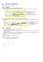
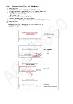
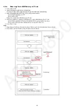
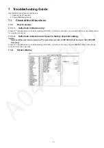
5.3.

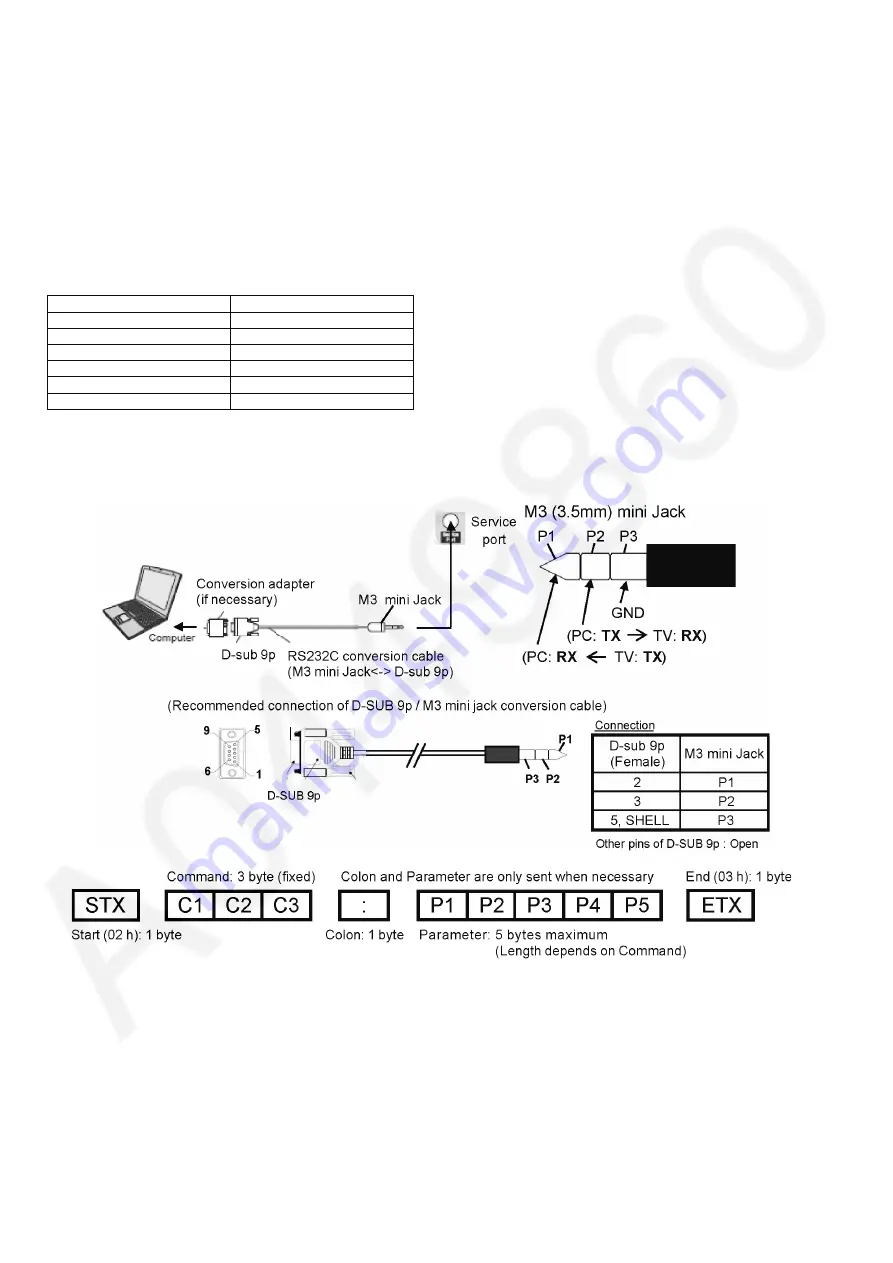
Service port (M3 mini Jack) Specifications

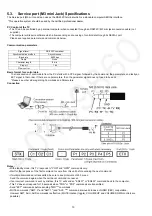
The Service port (M3 mini Jack) can use as the RS232C terminal which is a standard computer SERIAL interface.
 *This operation system should be used by the certified professional dealer.

PC Control of the TV

• The TV can be controlled by a personal computer when connected through an RS232C/ M3 mini jack conversion cable (not 

supplied).

• The computer will require software which allows sending and receiving of control data through its SERIAL port.

Please see required parameters and commands below.

Communication parameters

Basic format for control data

The transmission of control data from the PC starts with a STX signal, followed by the command, the parameters, and lastly an 
EXT signal in that order. If there are no parameters, then the parameter signal does not need to be sent.
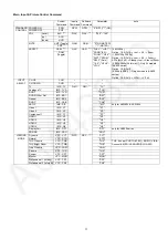
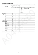
*Please see other side regarding Commands and Parameters.

Connection

Notes:

• With standby mode, this TV responds to "PON" and "QPW" commands only.
• Wait for the response of the first command to come from this unit before sending the next command.
• If multiple commands are transmitted, be sure to keep intervals of 250 m sec.

Send the command again when the call back command is unusual.

• If an incorrect command is sent by mistake, this TV will send an "ER401" or "ER402" command back to the computer.
• This TV does not respond for 15 seconds when "PON" or "POF" commands are transmitted.
• Send "EXT" commands before sending "IMS:**" commands.
• MUTE commands ("AMT: 0" and "AMT: 1") and "AVL: ***" command are invalid in case of HDMI (CEC) cooperation.

However AMT, AUU, AUD commands is effective. (MUTE rotation (toggle), VOLUME UP and VOLUME DOWN controls are 
possible.)

Signal level 

RS-232C compliant

Synchronization method 

Asynchronous

Baud rate 

9600 bps

Parity None

Character length 

8 bits

Stop bit 

1 bit

Flow control 

-

Summary of Contents for TX-58AXR800

Page 1: ... Panasonic Corporation 2014 Unauthorized copying and distribution is a violation of law ORDER NO PCZ1403051CE LCD Television Model No TX 58AX800E TX 58AXW804 TX 58AXR800 LA53 Chassis ...

Page 2: ...ervice Mode 14 6 2 Service tool mode 16 6 3 DRV Check USBHDD Check 17 6 4 Hotel mode 17 6 5 Data Copy by USB Memory 18 7 Troubleshooting Guide 21 7 1 Check of the IIC bus lines 21 7 2 Power LED Blinking timing chart 23 7 3 LCD Panel FR test mode 23 7 4 No Power 24 8 Disassembly and Assembly Instructions 25 8 1 Disassembly Flow Chart for the Unit 25 8 2 Disassembly Procedure for the Unit 26 8 3 Spe...

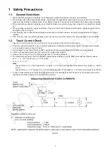
Page 3: ... 1 2 Touch Current Check 1 Plug the AC cord directly into the AC outlet Do not use an isolation transformer for this check 2 Connect a measuring network for touch currents between each exposed metallic part on the set and a good earth ground such as a water pipe as shown in Figure 1 3 Use Leakage Current Tester Simpson 228 or equivalent to measure the potential across the measuring network 4 Check...

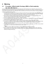
Page 4: ... of the assembly 3 Use only a grounded tip soldering iron to solder or unsolder ES devices 4 Use only an anti static solder removal device Some solder removal devices not classified as anti static ESD protected can generate electrical charge sufficient to damage ES devices 5 Do not use freon propelled chemicals These can generate electrical charges sufficient to damage ES devices 6 Do not remove a...

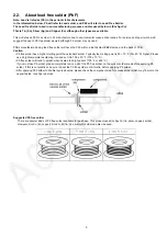
Page 5: ...ee solder has a higher melting point than standard solder Typically the melting point is 50 70 F 30 40 C higher Please use a high temperature soldering iron and set it to 700 20 F 370 10 C Pb free solder will tend to splash when heated too high about 1100 F or 600 C If you must use Pb solder please completely remove all of the Pb free solder on the pins or solder area before applying Pb solder If ...

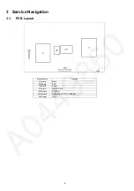
Page 6: ...6 3 Service Navigation 3 1 PCB Layout Board Name Function A Board Main FR Board FRC P Board Power K Board IR LED CATS GK Board SWITCH MD Board HUMAN ACTIVITY SENSOR HE Board HEVC ...

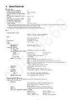
Page 7: ... 1 0 V p p 75 AUDIO L R RCA PIN Type 2 0 5 V rms Y 1 0 V p p including synchronisation PB CB PR CR 0 35 V p p HDMI 1 2 3 4 input TYPE A Connectors HDMI 1 3 3D Content Type Deep Colour x v Colour HDMI 2 3D Content Type Audio Return Channel Deep Colour x v Colour HDMI 4 4K 3D 3D content of 4K format is not supported Content Type Audio Return Channel Deep Colour x v Colour This TV supports HDAVI cont...

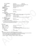
Page 8: ...s Resolution 1 920 1 080 Built in wireless LAN Standard compliance and Frequency range 2 IEEE802 11a n E W 5 180 GHz 5 320 GHz 5 500 GHz 5 580 GHz 5 660 GHz 5 700 GHz IEEE802 11a n R 5 15 GHz 5 35 GHz 5 47 GHz 5 85 GHz IEEE802 11b g n E W 2 412 GHz 2 472 GHz IEEE802 11b g n R 2 400 GHz 2 4835 GHz Security WPA2 PSK TKIP AES WPA PSK TKIP AES WEP 64 bit 128 bit Bluetooth wireless technology 3 Standar...

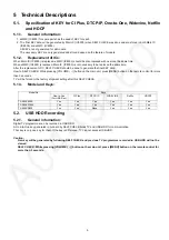
Page 9: ...al KEY data How to SELF CHECK While pressing VOLUME button on the main unit press MENU button on the remote control for more than 3 seconds TV will be forced to the factory shipment setting after this SELF CHECK 5 1 3 Model and Keys 5 2 USB HDD Recording 5 2 1 General information Digital TV programmes can be recorded in USB HDD A One to One key generated in A board by SELF CHECK binds TV and USB H...

Page 10: ...gnal does not need to be sent Please see other side regarding Commands and Parameters Connection Notes With standby mode this TV responds to PON and QPW commands only Wait for the response of the first command to come from this unit before sending the next command If multiple commands are transmitted be sure to keep intervals of 250 m sec Send the command again when the call back command is unusua...

Page 11: ...series Option 16 9 Full H Full V Full DAM Toggle INPUT SELECT CH UP CHU CH DOWN CHD TV IMS TV QMI QMI TV Analogue TV IMS TVA TVA DVB T IMS TVD TVD DVB S Other Sat IMS BS1 BS1 Freesat IMS BS2 BS2 DVB C IMS CAB CAB SAT IP IMS SIP SIP only for AXW804 ASW804 Video 1 IMS V1 V1 Video 2 IMS V2 V2 Component 1 IMS C1 C1 HDMI 1 IMS H1 H1 HDMI 2 IMS H2 H2 HDMI 3 IMS H3 H3 HDMI 4 IMS H4 H4 DisplayPort IMS DP1...

Page 12: ...1080i 1080p 2160pQFHD 2160p4KDCI 2160pQFHD 2160p4KDCI only for 4k models AX800 series DIRECT CH INPUT 0 ICH 0 1 ICH 1 2 ICH 2 3 ICH 3 4 ICH 4 5 ICH 5 6 ICH 6 7 ICH 7 8 ICH 8 9 ICH 9 MENU FUNCTION MENU MEN SELECT SEL RETURN RTN EXIT EXT ARROW LEFT ARL ARROW RIGHT ARR ARROW UP ARU ARROW DOWN ARD OPTION OSM RED RED GREEN GRN YELLOW YEL BLUE BLU APPS APS HOME HOM 3D O3D ...

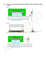
Page 13: ...13 5 4 How to connect and disconnect for FR12 and FR13 connectors on FR board ...

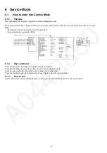
Page 14: ...d when 3D signal input Input 2D signal to enter Service Mode 6 1 2 Key command Press the 3 4 button to change the adjustment values or function Press the 1 2 button to step up down through the functions and adjustments Press the numerical button VOLUME to change of each option item Press the OK button after each adjustment has been made to store the required values 6 1 3 How to exit Switch off the...

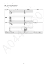
Page 15: ...em Sample Data Remark ADJUST CONTRAST 24E COLOR 2F TINT 00 SUB BRT 800 BACKLGT FFF H POS 0 H AMP 0 V POS 0 V AMP 0 WB ADJ R GAIN 80 G GAIN 78 B GAIN 7D R CENT 80 G CENT 80 B CENT 87 OPTION Boot ROM Factory Preset STBY SET 00 CLK MODE 00 CLOCK 000 EMERGENCY ON Y C Delay 0 OPT 1 00000100 OPT 2 11101110 OPT 3 00000001 OPT 4 00000010 EDID CLK SHIGH SRV TOOL 00 See Service tool mode DRV CHECK USBHDD CH...

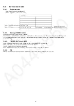
Page 16: ...t 2nd and 1st occurrence after shipment will be cleared by Self check indication and forced to factory shipment setting 6 2 3 POWER ON Time On Off Note To display TIME COUNT menu highlight position then press MUTE for 3 seconds Time Cumulative power on time indicated hour minute by decimal On Off Number of On Off switching by decimal Note This indication will not be cleared by either of the self c...

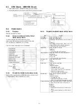
Page 17: ... AV1 AV2 HDMI1 HDMI2 HDMI3 HDMI4 DisplayPort Off give priority to a last memory Initial POS Select programme number Selection Off 0 to 99 Off give priority to a last memory Initial VOL Level Adjust the volume when each time power is switched on Selection Range Off 0 to 100 Off give priority to a last memory Maximum VOL Level Adjust maximum volume Range 0 to 100 Button Lock Select local key conditi...

Page 18: ...then copy to other TVs 6 5 2 Preparation Make pwd file as startup file for a or b in a empty USB Memory 1 Insert a empty USB Memory to your PC 2 Right click a blank area in a USB Memory window point to New and then click text document A new file is created by default New Text Document txt 3 Right click the new text document that you just created and select rename and then change the name and exten...

Page 19: ...llowing password for a or b by using remote control a For Board replacement 2770 b For Hotel 4850 Data will be copied from TV set to USB Memory It takes around 2 to 6 minutes maximum for copying 4 After the completion of copying to USB Memory remove USB Memory from TV set 5 Turn off the TV set Note Following new folder will be created in USB Memory for data from TV set a For Board replacement user...

Page 20: ...ent 2771 b For Hotel 4851 Data will be copied from USB Memory to TV set 4 After the completion of copying to USB Memory remove USB Memory from TV set a For Board replacement Data will be deleted after copying Limited one copy b For Hotel Data will not be deleted and can be used for other TVs 5 Turn off the TV set Note 1 Depending on the failure of boards function of Data copy for board replacement...

Page 21: ...pressing VOLUME button on the main unit press OK button on the remote control for more than 3 seconds 7 1 1 2 Self check indication and forced to factory shipment setting Caution New key will be generated and previous TV programmes recorded in USB HDD will not be viewed See USB HDD Recording Produce TV reception screen and while pressing VOLUME button on the main unit press MENU button on the remo...

Page 22: ...EEP A BOARD H91MEM2 IC8901 STM EEPROM A BOARD H30AVSW IC3000 AVSW A BOARD H17LAN IC8600 ETHERPHY A BOARD H00FE IC6800 DEMOD1 A BOARD H00SAT TU IC6803 DEMOD2 A BOARD H96ID ID A BOARD H97ID2 ID2 A BOARD H45BT BLUETOOTH A BOARD BLUETOOTH H42WiFi WiFi A BOARD WiFi H21DSP IC4900 AUDIO AMP A BOARD H52CAMERA CAMERA A BOARD CAMERA H36GCX IC9500 GCX1 MASTER FR BOARD H37GCX2 IC9600 GCX2 SLAVE FR BOARD H80HD...

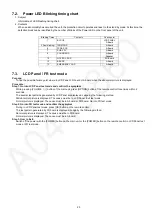
Page 23: ...isplayed Judge by the following method Still abnormal picture is displayed The cause must be in LCD Panel Exit test mode Normal picture is displayed The cause must be in A board or FR board Go into FR test mode Step 2 Go into FR test mode and confirm the symptom During in LCD Panel test mode press OK button on the remote control The test pattern generated by FR board is displayed Judge by the foll...

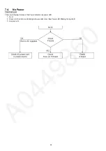
Page 24: ... Power First check point There are following 3 states of No Power indication by power LED 1 No lit 2 Green is lit then turns red blinking a few seconds later See Power LED Blinking timing chart 3 Only red is lit ...

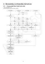
Page 25: ...25 8 Disassembly and Assembly Instructions 8 1 Disassembly Flow Chart for the Unit This is a disassembly chart When assembling perform this chart conversely ...

Page 26: ...oks 2 Remove the Rear Pedestal Cover 3 Remove the 4 screws 4 Remove the Rear Pedestal 8 2 2 Front Pedestal 1 Remove the 4 screws A 2 Remove the Front Pedestal Cover L R 3 Remove the 6 screws B 4 Remove the Front Pedestal 8 2 3 AC Inlet Cover and AC Cord 1 Remove the 1 screw 2 Remove the 4 hooks 3 Remove the AC Inlet Cover on AC Cord ...

Page 27: ...e AC Cord on P Board 8 2 4 Wi Fi Dongle 1 Remove the 1 screw 2 Remove the Wi Fi Dongle 8 2 5 BT Cover 1 Remove the 1 screw 2 Remove the BT Cover 8 2 6 Back Cover 1 Remove the 31 screws A 2 Remove the 1 screw B 3 Remove the 4 M6 Caps 4 Remove the Back Cover ...

Page 28: ...s 2 Disconnect the connectors P2 P4 and P5 3 Remove the P Board 4 Remove the P Board Barrier 8 2 8 A Board 1 Remove the 8 screws 2 Disconnect the connectors A02 A10 A12 A15 A16 A20 A23 A40 A41 and A43 3 Remove the A Board with the Heatsink ...

Page 29: ...with the Heatsink 8 2 10 HE Board 1 Remove the 3 screws 2 Disconnect the connectors HE40 HE41 and HE42 3 Remove the HE Board with the Heatsink 4 Remove the 4 screws 5 Remove the Heatsink HE Rear 8 2 11 GK Board 1 Disconnect the connector GK4 2 Remove the 1 hook 3 Remove the 1 hook 4 Remove the GK Board and the Key Button Bracket ...

Page 30: ... 3 Remove the Woofer 8 2 13 Wi Fi Cable 1 Remove the 1 screw 2 Remove the Wi Fi Cable 8 2 14 Camera Module 1 Disconnect the connector USB 2 Remove the 2 screws 3 Remove the Camera Module 8 2 15 Bluetooth Dongle 1 Disconnect the connector 2 Remove the Bluetooth Dongle ...

Page 31: ...er L 1 Remove the 2 screws A 2 Remove the 2 screws B 3 Remove the Ornament Cover L 8 2 19 Ornament Cover R 1 Remove the 2 screws A 2 Remove the 1 screw B 3 Remove the Ornament Cover R 8 2 20 Metal Bracket BTM 1 Remove the 6 screws 2 Remove the Metal Bracket BTM 8 2 21 Metal Bracket BTM L R 1 Remove the 4 screws 2 Remove the Metal Bracket BTM L R ...

Page 32: ...MD Board 1 Disconnect the connector M08 2 Remove the 2 hooks 3 Remove the MD Board 8 2 25 K Board 1 Remove the 2 hooks 2 Disconnect the connector K10 3 Remove the K Board 8 2 26 Speaker SQ L R 1 Remove the 4 hooks 2 Disconnect the 2 connectors 3 Remove the Speaker SQ L R 8 2 27 Ornament Case Assy 1 Remove the 2 screws 2 Remove the Ornament Case Assy ...

Page 33: ...overed by a soft cloth and a cushion 2 Remove the 16 screws A 3 Remove the 18 screws B 4 Remove the 4 Metal Frames the 4 Support Metal Frames and the Metal Rear Panel BTM 5 Remove the AL Cabinet Assy 8 2 29 LCD Panel Heatsink A Rear and Heatsink P Rear 1 Remove the 17 screws 2 Remove the LCD Panel the Heatsink A Rear and the Heatsink P Rear ...

Page 34: ...34 8 3 Specification of EMI countermeasures 8 3 1 Specification of sticking the gasket Front side of A board 1 8 3 2 Specification of sticking the gasket Back side of A board 1 ...

Page 35: ...35 8 3 3 Specification of sticking the gasket Back side of A board 2 8 3 4 Specification of sticking the gasket and the tape ...

Page 36: ...36 8 3 5 Specification of sticking the sponge 8 3 6 Specification of sticking the AL tape CI SLOT ...

Page 37: ...37 8 3 7 Specification of sticking the AL tape CI SLOT 8 3 8 Specification of sticking the AL tape CI SLOT ...

Page 38: ...38 8 3 9 Specification of sticking the Conductive tape CI SLOT 8 3 10 Specification of sticking the AL tape CI SLOT ...

Page 39: ...39 8 3 11 Specification of sticking the AL tape Gasket CI SLOT ...

Page 40: ...40 8 3 12 Specification of sticking Gasket CI SLOT Back cover side ...

Page 41: ...41 8 3 13 Specification of sticking the gasket Front side of A board 3 8 3 14 Specification of sticking the gasket Front side of A board 4 ...

Page 42: ...42 8 3 15 Specification of sticking the gasket near A board 8 3 16 Specification of sticking the gasket Back side of A board 3 ...

Page 43: ...43 8 3 17 Specification of sticking the gasket and the tape 8 3 18 Specification of sticking the gasket ...

Page 44: ...44 8 3 19 Specification of fixing the shield case 8 3 20 Specification of sticking the gasket near Bluetooth ...

Page 45: ...45 8 3 21 Specification of sticking the gasket 8 3 22 Specification of sticking the FELT Source PCB TOP Cover ...

Page 46: ...46 8 3 23 Specification of attaching the clamp core 8 3 24 Specification of sticking the gasket Back side of A board 4 ...

Page 47: ...47 8 3 25 Specification of fixing the shield case 8 3 26 Specification of sticking the rubber and gasket ...

Page 48: ...48 8 3 27 Specification of sticking the rubber and gasket 8 3 28 Specification of sticking the rubber ...

Page 49: ...49 8 3 29 Specification of sticking the gasket 8 3 30 Specification of sticking the gasket ...

Page 50: ...50 8 3 31 Specification of sticking the gasket 8 3 32 Specification of sticking the gasket ...

Page 51: ...51 8 3 33 Specification of sticking the gasket 8 3 34 Specification of sticking the gasket ...

Page 52: ...52 8 3 35 Specification of sticking the gasket 8 3 36 Specification of sticking the rubber and gasket ...

Page 53: ...53 8 3 37 Specification of sticking the gasket ...

Page 54: ...1 26V FPGA1 5V TP1807 1 44V 1 59V FPGA1 8V TP1811 1 71V 1 89V FPGA1 8V_2 TP1809 1 71V 1 89V FPGA2 5V TP1806 2 38V 2 63V DP3 3V TP1810 3 20V 3 50V DP1 2V TP1830 1 10V 1 28V HDMI1 1V TP1802 1 05V 1 19V LNB_PWR TP6702 12 8V 14 0V or 17 5V 19 0V TP6703 12 8V 14 0V or 17 5V 19 0V DMD_1 1V_2 TP5704 1 0V 1 21V REG_1 8V TP5702 1 70V 1 90V Power Supply Name Test point Spec PNL12V TP9295 9296 11 50V 12 50V ...

Page 55: ...W2852 SW2851 KEY1 SW2857 3 2 TO P5 POWER_ON K BOARD K10 7 3 4 5 6 1 SUB3 3V STBY3 3V RM2800 VCC OUT SN2800 AI 3 1 VCC OUT D2802 R G TO A10 REMOTE AI G_LED_ON R_LED_ON SUB3 3V AI STBY 3 3V STBY 3 3V R_LED_ON G_LED_ON REMOTE RL7101 9 12 Q7315 3PGS T7202 1 3 Q7203 4 3 T7302 14 9 P4 TO LD 24V 1 4 BL_SOS 9 BL_ON 10 P5 3 2 TO GK4 KEY 22 BL_ON BL_SOS SUB_ON 5VS 15 16V 12 7 Q7402 Q7404 24V Q7403 Q7405 16V...

Page 56: ...Main 65 64 63 62 60 59 57 56 55 54 53 52 50 49 47 46 75 76 73 74 96 95 94 93 91 90 88 87 77 78 32 ABCLK 30 ASDATA 35 ALRCLK 31 AMUTE 38 HDMI_IRQ 113 HDMI_XRST 120 28 26 25 23 22 20 19 17 14 12 11 9 8 6 5 3 RX1 HPDO0 5VDET0 IC3606 LS 6 7 2 3 DDCSDA DDCSCL ARC_OUT SPDIF_SW P30 BE COMMON AMUTE AA30 HDMI_IRQ W28 ABCLK ASDATA ALRCLK F31 D33 E34 CI I F TX0 TX1 IC1500 C1ZBZ0005254 FPGA L4 L3 N4 N3 R4 R3 ...

Page 57: ...C_XRST HEVC_SPDIF DCDCEN2 HEVC_INT DMD IIC_3 16V PA2000 DCDCIN D5402 DCDCIN2 5 4 WOL3 3V STB5 3V VJ5400 STB5V VBUS IC8601 Reg 16V IC1802 DC DC 6 8 HDMI1 1V 1 DCDCEN 16V IC5440 DC DC 7 8 2 USB5V 3 DCDCEN 16V IC5400 DC DC 6 8 SUB3 3V 1 DCDCEN 16V IC5420 DC DC 6 8 SUB5V 1 DCDCEN DCDCIN IC8100 DC DC 8 5 SUB1 1V 4 DCDCEN DCDCIN2 IC8101 DC DC 6 8 SUB1 5V 1 DCDCEN2 DCDCIN IC8100 DC DC 8 5 SUB1 1V 4 DCDCE...

Page 58: ... DCDCEN 51 BL_ON AB18 AB21 AE25 IC9600 MN85063AP IMAGE PROCESSOR GCX 2 PWM_ENB OEBLK LOGO_ON 2 0 S E 7 0 D E W X R E S C E X F20 G20 E22 E23 F21 F22 G21 G22 V20 U20 W20 U21 V21 AA18 AA19 AE25 GCX GPIO GLASS_RF LOGO_ON 2 0 S E 7 0 D E W X R E S C E X F20 G20 E22 E23 F21 F22 G21 G22 V20 U20 W20 U21 V21 IC9500 MN85063AP IMAGE PROCESSOR GCX 1 GCX GPI0 SYSTEM BUS GCX GPI0 SYSTEM BUS BL_ON E6 BL_ON_INPU...

Page 59: ...59 11 Wiring Connection Diagram 11 1 Wiring Diagram ...

Page 60: ...ion statement Caution Please confirm that all flexible cables are assembled correctly Also make sure that they are locked in the connectors Verify by giving the flexible cables a very slight pull 11 3 Dressing Wire ...

Page 61: ...61 ...

Page 62: ...62 ...

Page 63: ...63 ...

Reviews: