N ote: Lead is listed as (P b ) in th e p e rio d ic ta b le o f e le m en ts.
In th e in fo rm atio n below , Pb w ill re fe r to Lead so lder, and P bF w ill re fe r to Lead F ree Solder.
T h e Lead F ree S o ld e r used in o u r m a n u fac tu rin g p ro ces s and d is c u s s e d b elo w is (S n + A g + C u ).
T h a t is Tin (Sn), S ilv e r (A g ) and C o p p e r (C u ) a lth o u g h o th e r ty p e s are availab le .
T h is m odel uses Pb Free s o ld e r in it's m a n u fa ctu re due to e n v iro n m e n ta l co n s e rv a tio n issues. F or service and rep air w ork, w e 'd
s u g g e s t the use o f Pb free s o ld e r as well, alth ou gh Pb s o ld e r m ay be used.
P C B s m a n ufacture d using lead free s o ld e r w ill have th e P bF w ith in a le a f S ym bo l
Pb F
stam ped on th e ba ck o f PCB.
C autio n
• Pb free s o ld e r has a high er m elting po in t tha n stan dard solder. T ypica lly th e m elting po in t is 50 ~ 70 °F (30 ~ 4 0 °C ) higher. P lease
use a high te m p e ra tu re solde ring iron and se t it to 700 ± 20 °F (370 ± 10 °C).
• Pb free s o ld e r w ill ten d to splash w h e n heated too high (ab ou t 1100 °F or 6 0 0 °C).
If you m ust use Pb solder, please c o m p le te ly rem ove all o f th e Pb free s o ld e r on th e pins or s o ld e r area before ap plying Pb s o l
der. If th is is not practical, be sure to he at th e Pb free s o ld e r until it m elts, before ap plying Pb solder.
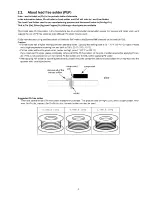
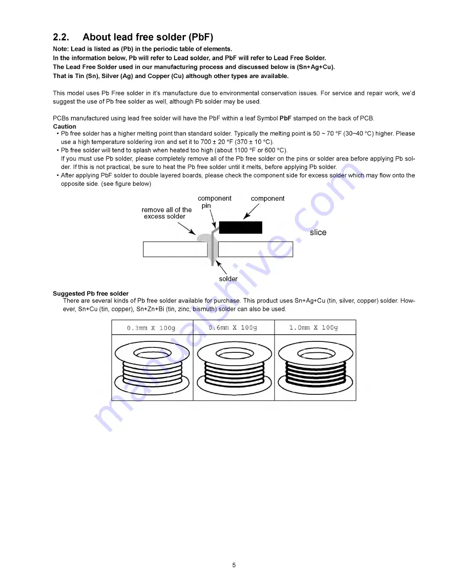
• A fte r ap plying PbF s o ld e r to do ub le layered boards, please c h e c k th e co m p o n e n t side fo r exce ss s o ld e r w h ic h m ay flo w onto th e
op po site side. (see fig u re below )
component
component
remove all of the
^ 1П\
excess solder
2.2.
About lead free solder (PbF)
slice
\
solder
S u g g e s te d Pb fre e s o ld e r
T h e re are seve ral kinds o f Pb free s o ld e r ava ila b le fo r purchase. T his pro du ct uses S n + A g + C u (tin, silver, co p p e r) solder. H o w
ever, S n+ C u (tin, copper), S n+ Z n+ B i (tin, zinc, bism uth) s o ld e r can also be used.
5
Summary of Contents for TX-PR65VT20
Page 23: ...7 4 No Picture 23 ...
Page 38: ...38 ...
Page 39: ...11 Block Diagram 11 1 Main Block Diagram 39 ...
Page 40: ...11 2 Block 1 5 Diagram 40 ...
Page 41: ...Block 2 5 Diagram ...
Page 42: ...11 4 Block 3 5 Diagram г а P O W E R S U P P LY 42 ...
Page 44: ...11 6 Block 5 5 Diagram S C S C A N D R IV E 44 ...
Page 45: ......
Page 47: ...12 3 Wiring 2 46 ...
Page 48: ...12 5 Wiring 4 12 6 Wiring 5 47 ...
Page 49: ...12 7 Wiring 6 48 ...
Page 52: ...13 2 P MAIN Board 1 3 Schematic Diagram 50 ...
Page 53: ...13 3 P MAIN Board 2 3 Schematic Diagram A B C D E F i 2 3 4 5 6 7 51 ...
Page 55: ...13 5 P SUB Board Schematic Diagram 53 ...
Page 57: ...13 7 A Board 2 25 Schematic Diagram A A BOARD 2 25 Peaks DEST 55 ...
Page 61: ...41 4 2 4 3 4 4 4 5 58 ...
Page 63: ...A A BOARD 7 25 GenX8 13 12 A Board 7 25 Schematic Diagram 5 5 5 6 5 7 5 8 5 9 60 ...
Page 64: ...60 61 62 6 3 ...
Page 67: ...Peaks Com mon 7 8 79 8 0 81 ...
Page 69: ...86 8 7 88 89 9 0 63 ...
Page 76: ...131 1 3 2 1 3 3 1 3 4 13 5 68 ...
Page 85: ...IC 5 5 0 0 C0DBAYY0071 5 2 0 4 2 0 5 2 0 6 2 0 7 ...
Page 89: ...5 1 6 1 7 1 8 1 9 79 ...
Page 90: ...13 32 D Board 2 5 Schematic Diagram 10 1 11 1 12 1 13 1 14 1 15 1 16 1 1 7 1 18 80 ...
Page 91: ...13 33 D Board 3 5 Schematic Diagram 19 1 2 0 1 21 1 2 2 1 2 3 1 2 4 1 2 5 1 2 6 1 2 7 81 ...
Page 92: ...13 34 D Board 4 5 Schematic Diagram 2 8 2 9 30 31 32 3 3 3 4 3 5 3 6 82 ...
Page 93: ...13 35 D Board 5 5 Schematic Diagram 37 38 3 9 4 0 41 4 2 4 3 4 4 4 5 83 ...
Page 94: ...13 36 C1 Board Schematic Diagram A B C D E A C1 BOARD TXNC11LPUJ C20 F 1 2 3 4 5 84 ...
Page 97: ...13 39 C3 Board 1 2 Schematic Diagram F 1 2 3 4 5 87 ...
Page 98: ...13 40 C3 Board 2 2 Schematic Diagram A 10 I 11 12 13 14 C3 BOARD TXNC31 LPUJ 2 2 88 ...
Page 99: ...15 16 17 18 ...
Page 100: ...13 41 C4 Board Schematic Diagram A B C D E A C4 BOARD TXNC41LPUJ C50 F 1 2 3 89 ...
Page 103: ...13 44 C6 Board 1 2 Schematic Diagram A C6 BOARD TXNC61LPUJ 1 2 A 92 ...
Page 105: ...ь fbtq CA14 1 ь I CA15 я 15 16 17 18 ...
Page 107: ...13 47 SC Board 2 4 Schematic Diagram 10 I 11 1 12 1 13 1 14 1 1 5 1 16 1 17 1 18 95 ...
Page 108: ...13 48 SC Board 3 4 Schematic Diagram 19 1 2 0 1 21 1 2 2 1 2 3 1 2 4 1 2 5 1 2 6 1 2 7 96 ...
Page 109: ...13 49 SC Board 4 4 Schematic Diagram 2 8 2 9 3 0 31 3 2 3 3 3 4 3 5 3 6 97 ...
Page 115: ...P MAIN BOARD COMPONENT SIDE ETX2MM813MDM 6 5 4 3 2 1 A I B I C I D I E I F I G I H I I 102 ...
Page 119: ...14 4 A Board A BOARD FOIL SIDE A PR65VT20 т а B G 6 5 4 3 2 1 E F H 106 ...
Page 120: ...A BOARD COMPONENT SIDE A PR65VT20 6 5 4 3 2 1 A I B I C I D I E I F I G I H I I 107 ...
Page 121: ...14 5 D Board 108 ...
Page 122: ...6 D BOARD COMPONENT SIDE TZTNP01LCUE A I В I С I D ...
Page 123: ......
Page 124: ...14 6 C1 Board C1 BOARD COMPONENT SIDE TXNC11LPUJ 1 A I B I C I D I E I F I G I H I I 110 ...
Page 126: ...14 8 C3 Board C3 BOARD FOIL SIDE TXNC31LPUJ 6 5 4 3 1 A I B I C I D I E I F I G I H I I 112 ...
Page 127: ...14 9 C4 Board 113 ...
Page 129: ...14 11 C6 Board 3 C6 BOARD COMPONENT SIDE TXNC61LPUJ 1 A I B I C I D I E I F I G I H I I 115 ...
Page 130: ...14 12 SC Board SC BOARD FOIL SIDE TXNSC1LPUJ В 116 ...
Page 131: ......
Page 132: ... SC BOARD COMPONENT SIDE TXNSC1LPUJ 6 5 4 3 2 1 A I B I C I D I E I F I G I H I I 117 ...
Page 133: ...14 13 SS Board 1 A I B I C I D I E I F I G I H I I 118 ...
Page 134: ...1 A I B I C I D I E I F I G I H I I 119 ...
Page 137: ...15 1 2 Exploded View 2 122 ...
Page 138: ...123 ...
Page 139: ...15 1 4 Packing 2 124 ...

