11
5.3.
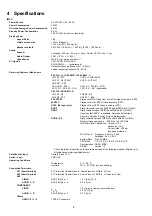
Service port (M3 mini Jack) Specifications
The Service port (M3 mini Jack) on the following TVs can use as the RS232C terminal which is a standard computer SERIAL inter-
face.
*This operation system should be used by the certified professional dealer.
PC Control of the TV
• The TV can be controlled by a personal computer when connected through an RS232C/ M3 mini jack conversion cable (not sup-
plied).
• The computer will require software which allows sending and receiving of control data through its SERIAL port.
Please see required parameters and commands below.
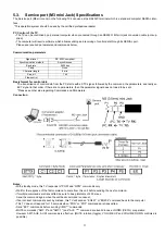
Communication parameters
Basic format for control data
The transmission of control data from the PC starts with a STX signal, followed by the command, the parameters, and lastly an
EXT signal in that order. If there are no parameters, then the parameter signal does not need to be sent.
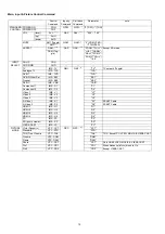
*Please see other side regarding Commands and Parameters.
Connection
Notes:
• With standby mode, this TV responds to "PON” and “QPW” commands only.
• Wait for the response of the first command to come from this unit before sending the next command.
• If multiple commands are transmitted, be sure to keep intervals of 250 m sec.
Send the command again when the call back command is unusual.
• If an incorrect command is sent by mistake, this TV will send an “ER401” or “ER402” command back to the computer.
• This TV does not respond for 15 seconds when “PON” or “POF” commands are transmitted.
• Send “EXT” commands before sending “IMS:**” commands.
• MUTE commands ("AMT: 0" and "AMT: 1") and "AVL: ***" command are invalid in case of HDMI (CECIL) cooperation.
However AMT, AUK, AUDI commands is effective. (MUTE rotation (toggle), VOLUME UP and VOLUME DOWN controls are
possible.)
Signal level
RS-232C compliant
Synchronization method
Asynchronous
Baud rate
9600 bps
Parity None
Character length
8 bits
Stop bit
1 bit
Flow control
-
Summary of Contents for TXP50VT20L
Page 24: ...24 7 4 No Picture ...
Page 46: ...46 ...
Page 48: ...48 12 3 Wiring 2 12 4 Wiring 3 ...
Page 49: ...49 12 5 Wiring 4 ...
Page 50: ...50 12 6 Wiring 5 ...
Page 51: ...51 13 Schematic Diagram 13 1 Schematic Diagram Note ...
Page 104: ...104 A B C D E F G H I 1 2 3 4 5 6 P BOARD COMPONENT SIDE ETX2MM806MVH ...
Page 122: ...122 15 1 2 Exploded View 2 ...
Page 123: ...123 15 1 3 Packing 1 ...
Page 124: ...124 15 1 4 Packing 2 ...
Page 125: ...125 15 1 5 Mechanical Replacement Parts List ...
Page 129: ...129 15 2 Electrical Replacement Parts List 15 2 1 Replacement Parts List Notes ...


