background image

66

Mantenimiento

Español

Ubicación de la instalación

Precauciones durante el uso

Precauciones durante los cambios de ubicación

Mantenimiento

Entre los lugares donde no se debe instalar el panel táctil están los siguientes:

•  Lugares expuestos a la luz solar directa y aquellas cerca de fuertes fuentes de luz 

(El equipo es un panel táctil óptico que utiliza rayos infrarrojos y puede funcionar de forma incorrecta si se ve afectado por condiciones adversas.)

•  Lugares polvorientos o húmedos
•  Lugares que pueden estar expuestos a impactos o vibraciones
•  Lugares cercanos a emisiones de productos químicos o vapor de agua, o lugares donde el aparato pueda entrar en contacto 

con sustancias químicas

•  Lugares cercanos a fuentes de ruido eléctrico (generadores, aparatos de aire acondicionado, etc.)

No toque el área de transmisión de infrarrojos ni la pantalla hasta que el sistema 
operativo se inicie después de encender el ordenador.

•  Dicha acción será interpretada por los detectores como elementos defectuosos lo que producirá 

problemas de funcionamiento. Si esto ocurriese, reinicie el ordenador. Igualmente no toque el 
área de transmisión de infrarrojos ni la pantalla al conectar y desconectar el cable USB.

Cuando use otros dispositivos que utilicen rayos infrarrojos, manténgalos alejados 
del equipo para evitar un mal funcionamiento.

Utilice solamente el lápiz táctil que se incluye con este equipo. Si se usan otros 
productos no se garantiza el funcionamiento.

Al utilizar el panel táctil tenga cuidado de no aplicar una carga excesiva presionando 
sobre la estructura del panel o de cualquier otra forma. 

Evite que el equipo reciba cualquier impacto durante los cambios de ubicación. De no hacerlo así se podrían producir fallos de funcionamiento.

Sujete el dispositivo principal cuando realice un cambio de ubicación.

•  Agarrar este equipo en esta situación puede causar problemas.

No sujete el cable USB durante los cambios de ubicación.

•  De lo contrario se podrían producir daños en el cable USB y con ello fallos en el funcionamiento.

* Asegúrese de desenchufar el cable USB antes de limpiar el equipo.

Utilice un paño suave y quite delicadamente la suciedad de la super

fi

 cie del equipo.

•  Si la suciedad es persistente moje un paño con una disolución de 1 parte de detergente neutral en 100 partes de agua, 

escúrralo bien, pase el paño por la zona sucia y luego séquela bien con un paño seco.

•  Si cayesen gotas dentro, tanto el equipo como la pantalla del dispositivo principal podrían fallar. No frote tampoco la pantalla con fuerza.

Utilice un paño suave y quite la suciedad del área de transmisión de infrarrojos.

•  Una vez al día, limpie con un paño suave cualquier suciedad o residuo que se haya acumulado sobre el área de transmisión 

de infrarrojos. De lo contrario, el funcionamiento será defectuoso, aunque en tal caso puede restablecerse el funcionamiento 
normal limpiando la suciedad con un paño suave.

•  Si la suciedad es persistente moje un paño con una disolución de 1 parte de detergente neutral en 100 partes de agua, 

escúrralo bien, pase el paño por la zona sucia y luego séquela bien con un paño seco.

No aplique ningún detergente ni directamente ni con un aerosol.

•  Si cayesen gotas dentro el equipo podría fallar.

No aplique sustancias volátiles como insecticidas, benceno o disolvente.

•  Se puede deteriorar el panel o puede perder el revestimiento.

No mantenga el equipo en contacto con materiales de goma o plástico durante un periodo de tiempo prolongado.

•  La carcasa podría deteriorarse.
•  Cuando utilice algún tipo de toallita limpiadora con productos químicos, siga las instrucciones que con ella se proporcionen.

La limpieza del interior debe realizarse por lo menos una vez al año. Para instrucciones sobre cómo realizar esta limpieza, pregunte a su distribuidor.

•  Si se acumula polvo en el interior, disminuye el nivel de luz infrarroja disponible para la detección táctil y el funcionamiento 

puede deteriorarse. Pregunte a su distribuidor cómo se debe efectuar la limpieza interna por lo menos una vez al año.

Área de 

transmisión de 

infrarrojos

Summary of Contents for TY-TP65P30K ()

Page 1: ...2P30K TY TP50P30K TY TP60P30K TY TP65P30K Mode d emploi cran Tactile Manual de instrucciones Panel T ctil Operating Instructions Touch Panel Bedienungsanleitung Touch Panel Manuali di istruzioni Touch...

Page 2: ...2...

Page 3: ...griffbereit auf Prima di collegare far funzionare o regolare questo prodotto leggere completamente queste istruzioni Conservare questo manuale per riferimenti futuri Avant d effectuer les connexions...

Page 4: ...4 4 6 7 8 9 11 11 12 13 13 14...

Page 5: ...5 2...

Page 6: ...6 USB USB USB 100 1 1 100 1 1 OS USB...

Page 7: ...7 2 2 USB CD ROM Windows Microsoft Corporation Windows Microsoft Windows Operating System...

Page 8: ...8 2 2 42V 13 V V 1 2 3 4 5 1 2 3 4 5 6...

Page 9: ...9 2 USB B A B 2 3...

Page 10: ...10...

Page 11: ...11 IBM PC AT USB Windows XP SP2 32bit 64bit Windows Vista 32bit 64bit Windows 7 32bit 64bit USB USB CD ROM Windows7 WindowsXP Vista CD ROM USB A USB USB A USB A USB 5m...

Page 12: ...520 1105 615 1330 750 1435 805 1 0 1481 833 1769 985 2129 1201 2297 1289 2 5 2 5 186 105 222 124 267 151 288 162 5 0 5 0 7 0 7 0 USB1 1 DATA DATA VCC GND 0 40 25 Hr 1 20 80 1 2000 lx 20 10000 lx 90 10...

Page 13: ...V A 1028 2 1218 2 1442 2 1562 2 B 618 2 732 2 860 2 933 2 C 621 4 735 4 863 4 936 4 1 2 3 4 5 6 1 2 3 4 5 6 1 2 3 4 5 6 1 2 3 4 5 6 7 7 8 9 1 2 3 4 5 6 1 2 3 4 5 6 7 50V 60V 65V A 47 47 47 47 B 12 C 7...

Page 14: ...14 CD ROM USB 8 8 1 3 2 1 571 8504 1 15 06 6905 5574 Panasonic Corporation 2012...

Page 15: ...15 15 16 17 18 19 21 21 22 23 23...

Page 16: ...16 USB USB USB USB USB 100 100...

Page 17: ...17 1 A 2 B 4 A 8 A 2 B 8 USB 1 1 1 2 Windows Microsoft Windows Microsoft Windows...

Page 18: ...18 A A 8 8 A A 42V 23 A A 42V 42V A A...

Page 19: ...19 1 USB 2 B 3 B A B B 2 3 B B B B...

Page 20: ...20 4 5...

Page 21: ...21 USB IBM PC AT Windows XP SP2 32 64 Windows Vista 32 64 Windows 7 SP1 32 64 USB USB CD ROM Windows 7 Windows XP Vista CD ROM USB USB A USB USB A USB A USB USB USB...

Page 22: ...mm 1 0 mm 1 481 833 1 769 985 2 129 1 201 2 297 1 289 2 5 mm 2 5 mm 186 105 222 124 267 151 288 162 5 0 mm 5 0 mm 7 0 mm 7 0 mm USB1 1 DATA DATA VCC GND 0 40 C 25 C Hr 1 20 80 1 2 000 lx 20 10 000 lx...

Page 23: ...23 mm mm 42V 50V 60V 65V A 1 028 2 1 218 2 1 442 2 1 562 2 B 618 2 732 2 860 2 933 2 C 621 4 735 4 863 4 936 4 50V 42V 18 60V 65V...

Page 24: ...24 1006 http panasonic cn 5 C 3 6 2012 2 Panasonic 8008100781 800 4008100781 Panasonic Corporation 2012...

Page 25: ...not insert or let metal objects or combustible materials in the equipment because that may cause a fire or electric shock Pay special attention to children s behavior Do not use the equipment with an...

Page 26: ...ing Doing so may damage the USB cable resulting in a failure Be sure to unplug the USB cable before cleaning the equipment Use a soft cloth and lightly wipe off dirt on the surface of the equipment If...

Page 27: ...Instructions 1 Touch pen 2 Illustrations are conceptual views and may differ in shape from the actual equipment The specifications of the product are subject to change without notice Windows is a reg...

Page 28: ...them Mounting in vertical posture Check in the figure below the positions where the brackets are attached and remove the screws 8 in total from top and bottom sides Attach the mounting brackets A for...

Page 29: ...same Mount in the way that the USB port becomes lower left when seen from the front 2 Prepare the mounting brackets B 3 As shown in the figure below attach the mounting brackets B to the mounting brac...

Page 30: ...fter adjusting the position completely tighten the screws which were temporarily fixed Note that tightening the screws too tight may deform the bracket Notes There should not be a space between the to...

Page 31: ...he installation manual of the driver software included in the supplied CD ROM for connection of the USB extension cable and setup of the touch panel driver software Operating Conditions Computer USB c...

Page 32: ...tch 5 0 mm W 5 0 mm H Minimum stylus 7 0 mm W 7 0 mm H Interface USB1 1 compliant Signals DATA DATA VCC GND Temperature When operating 0 40 C Temperature gradient 25 C Hr or less 1 Humidity When opera...

Page 33: ...ensions Unit mm 42V 50V 60V 65V A 1028 2 1218 2 1442 2 1562 2 B 618 2 732 2 860 2 933 2 C 621 4 735 4 863 4 936 4 1 2 3 4 5 6 1 2 3 4 5 6 1 2 3 4 5 6 1 2 3 4 5 6 7 7 8 9 1 2 3 4 5 6 1 2 3 4 5 6 7 For...

Page 34: ...ent of theft or loss and for Warranty Service purposes Warranty conditions are managed by distributors to meet the standards set by each country For details contact your dealer where you made your pur...

Page 35: ...bjekte oder brennbaren Materialien in das Ger t bzw lassen Sie solche nicht ins Ger t gelangen da ansonsten die Gefahr von Brandausbruch und elektrischem Schlag besteht Achten Sie besonders auf das Ve...

Page 36: ...was zu einer Fehlfunktion f hren kann Achten vor dem Reinigen des Ger tes unbedingt darauf das USB Kabel abzutrennen Verwenden Sie ein weiches Tuch um sachte Schmutz von der Oberfl che des Ger tes abz...

Page 37: ...1 Touch Pen 2 Die Abbildungen sind konzeptionelle Ansichten und k nnen in ihrer Form von der tats chlichen Ausstattung abweichen Die technischen Daten des Produkts k nnen ohne vorherige Ank ndigung ge...

Page 38: ...e berpr fen Sie in der Abbildung unten die Positionen an denen die Montageb gel befestigt sind und entfernen Sie die Schrauben 8 insgesamt von der Ober und Unterseite Befestigen Sie die Montageb gel A...

Page 39: ...iche F hren Sie die Montage so durch dass die USB Schnittstelle sich unten links befindet wenn man von vorne schaut 2 Bereiten Sie die Halteb gel B vor 3 Wie in der Abbildung unten gezeigt befestigen...

Page 40: ...er Position machen Sie die zeitweilig befestigten Schrauben fest Beachten Sie dass ein allzu strammes Festmachen der Schrauben den B gel verformen kann Hinweise Es sollte kein leeren Raum zwischen dem...

Page 41: ...Treiber Software auf der mitgelieferten CD ROM f r den Anschluss des USB Verl ngerungskabels und den Setup der Touch Panel Treiber Software Betriebsbedingungen Computer USB Steckverbinder Typ A Buchs...

Page 42: ...5 0 mm B 5 0 mm H Minimalgr e des Stifts 7 0 mm B 7 0 mm H Schnittstelle USB1 1 kompatibel Signale DATA DATA VCC GND Temperatur Beim Betrieb 0 40 C Temperatur gradient 25 C Hr oder weniger 1 Luftfeuc...

Page 43: ...Einheit mm 42V 50V 60V 65V A 1 028 2 1 218 2 1 442 2 1 562 2 B 618 2 732 2 860 2 933 2 C 621 4 735 4 863 4 936 4 1 2 3 4 5 6 1 2 3 4 5 6 1 2 3 4 5 6 1 2 3 4 5 6 7 7 8 9 1 2 3 4 5 6 1 2 3 4 5 6 7 F r...

Page 44: ...und als Kundendienst Garantie behilflich ist Garantiebedingungen werden vom Vertreiber ausgearbeitet um den f r das jeweilige Land geltenden Standards zu entsprechen F r weitere Hinweise wenden Sie si...

Page 45: ...o far penetrare oggetti metallici o materiali combustibili nel prodotto per evitare incendi o scosse elettriche Prestare particolare attenzione ai bambini Non utilizzare il prodotto con dispositivi di...

Page 46: ...arsi e causare malfunzionamenti Staccare sempre il cavo USB prima di pulire il prodotto Utilizzare un panno morbido e spolverare delicatamente la superficie del prodotto Se il prodotto molto sporco in...

Page 47: ...ver Manuali di istruzioni 1 Penna 2 Le illustrazioni sono concettuali e potrebbero differire dal prodotto reale Le specifiche del prodotto sono soggette a modifiche senza preavviso Windows un marchio...

Page 48: ...ente figura controllare le posizioni di montaggio delle staffe e rimuovere le viti 8 in totale tra il lato superiore e inferiore Fissare le staffe di montaggio A per il lato superiore e inferiore con...

Page 49: ...do che la porta USB si trovi in basso a sinistra guardandola dal lato anteriore 2 Preparare le staffe di montaggio B 3 Come illustrato nella seguente figura agganciare le staffe di montaggio B alle st...

Page 50: ...mentazione 5 Dopo aver regolato la posizione stringere a fondo le viti serrate temporaneamente Tenere presente che un eccessivo serraggio delle viti pu deformare la staffa Note Tra il Touch Panel e la...

Page 51: ...el software del driver incluso sul CD ROM in dotazione per informazioni sul collegamento del cavo di prolunga USB e sulla configurazione del software del driver del Touch Panel Condizioni di funzionam...

Page 52: ...Dimensioni minime strumento di input 7 0 mm L 7 0 mm A Interfaccia Conforme USB1 1 Segnali DATA DATA VCC GND Temperatura Durante il funzionamento 0 40 C gradiente di temperatura 25 C ora o inferiore...

Page 53: ...sioni esterne Unit mm 42V 50V 60V 65V A 1 028 2 1 218 2 1 442 2 1 562 2 B 618 2 732 2 860 2 933 2 C 621 4 735 4 863 4 936 4 1 2 3 4 5 6 1 2 3 4 5 6 1 2 3 4 5 6 1 2 3 4 5 6 7 7 8 9 1 2 3 4 5 6 1 2 3 4...

Page 54: ...i fini dell assistenza in garanzia Le condizioni di applicazione della garanzia ricadono sotto la responsabilit dei distributori che si occupano di operare nel rispetto delle norme in vigore nei singo...

Page 55: ...ans l quipement N ins rez ou ne laissez aucun objet m tallique ou d autres mat riaux combustibles p n trer dans l quipement car cela pourrait entra ner un incendie ou une lectrocution Faites particuli...

Page 56: ...ndommager le c ble USB et provoquer un dysfonctionnement Assurez vous de d brancher le c ble USB avant de nettoyer l appareil Utilisez un linge doux et nettoyez l g rement la salet sur la surface de l...

Page 57: ...tactile 2 Les illustrations sont des vues conceptuelles et leur forme pourra diff rer de l quipement actuel Les sp cifications du produit sont sujettes des modifications sans pr avis Windows est une...

Page 58: ...rticale V rifiez sur la figure ci dessous les positions dans lesquelles les supports sont fix s et retirez les vis 8 au total en haut et en bas Fixez les supports de fixation A en haut et en bas avec...

Page 59: ...rticale est la m me Effectuez le montage de sorte que le port USB soit en bas gauche lorsque l cran est vu de face 2 Pr parez les supports de fixation B 3 Comme montr dans la figure ci dessous fixez l...

Page 60: ...pr s avoir ajust la position serrez compl tement les vis temporairement fix es Notez que trop serrer les vis pourrait d former le support Remarques Il ne devrait y avoir aucun espace entre l cran tact...

Page 61: ...escriptions du guide d installation du logiciel du pilote inclus sur le CD ROM fourni pour la connexion de la rallonge USB et la configuration du logiciel du pilote de l cran tactile Conditions de fon...

Page 62: ...5 0 mm H Stylet minimum 7 0 mm L 7 0 mm H Interface Compatible USB1 1 Signaux DATA DATA VCC GND Temp rature Pendant le fonctionnement 0 40 C Gradient de temp rature 25 C Hr ou moins 1 Humidit Pendant...

Page 63: ...sions externes Unit s mm 42V 50V 60V 65V A 1 028 2 1 218 2 1 442 2 1 562 2 B 618 2 732 2 860 2 933 2 C 621 4 735 4 863 4 936 4 1 2 3 4 5 6 1 2 3 4 5 6 1 2 3 4 5 6 1 2 3 4 5 6 7 7 8 9 1 2 3 4 5 6 1 2 3...

Page 64: ...il en cas de vol ou de perte et pour l utilisation des services de garantie Les conditions de la garantie sont trait es par les distributeurs pour se conformer aux standards de chaque pays Pour les d...

Page 65: ...nflamables en el equipo porque esto podr a ocasionar un incendio o una descarga el ctrica Preste especial atenci n a las acciones de los ni os No utilice el equipo con ning n otro dispositivo que no s...

Page 66: ...ubicaci n De lo contrario se podr an producir da os en el cable USB y con ello fallos en el funcionamiento Aseg rese de desenchufar el cable USB antes de limpiar el equipo Utilice un pa o suave y qui...

Page 67: ...til 2 Las ilustraciones son im genes que representan un concepto y por tanto pueden tener una forma distinta al dispositivo real Las especificaciones del producto est n sujetas a cambios que pueden re...

Page 68: ...ci n para ver el lugar en el que se ajustan los adaptadores de montaje y retire los tornillos 8 en total de los lados superior e inferior Fije los adaptadores de montaje A para los lados superior e in...

Page 69: ...orma que el puerto USB se encuentre en la parte inferior izquierda seg n se mira a la parte frontal del panel 2 Prepare los adaptadores de montaje B 3 Tal como se muestra en la figura a continuaci n f...

Page 70: ...z ajustada la posici n apriete bien los tornillos que hab a colocado de forma temporal Tenga en cuenta que apretar excesivamente los tornillos puede deformar el adaptador de montaje Notas No debe qued...

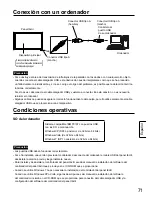
Page 71: ...incluido en el CD ROM que se proporciona para conexi n del cable alargador USB y la configuraci n del software del controlador del panel t ctil Condiciones operativas Ordenador Conector USB tipo A hem...

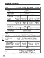
Page 72: ...Paso del elemento ptico 5 0 mm An 5 0 mm Al Medida m nima del l piz 7 0 mm An 7 0 mm Al Interfaz Compatible con USB1 1 Se ales DATA DATA VCC GND Temperatura De funcionamiento 0 40 C gradiente de tempe...

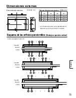
Page 73: ...ensiones externas Unidades mm 42V 50V 60V 65V A 1 028 2 1 218 2 1 442 2 1 562 2 B 618 2 732 2 860 2 933 2 C 621 4 735 4 863 4 936 4 1 2 3 4 5 6 1 2 3 4 5 6 1 2 3 4 5 6 1 2 3 4 5 6 7 7 8 9 1 2 3 4 5 6...

Page 74: ...y para poder hacer uso del servicio que ofrece la garant a Las condiciones de la garant a corren a cargo de los distribuidores para satisfacer as las normas vigentes en cada pa s Para conocer detalles...

Page 75: ...75 75 76 77 78 79 81 81 82 83 83 Panasonic...

Page 76: ...76 USB USB USB USB 1 100 1 100...

Page 77: ...77 1 A 2 B 4 A 8 A 2 B 8 USB 1 CD ROM 1 1 2 Windows Microsoft Corporation Windows Microsoft Windows...

Page 78: ...78 A A 2 8 8 A A 2 42V 83 1 2 3 4 5 6 A A 42V 42V 1 2 3 4 5 A A...

Page 79: ...79 1 USB 2 B 3 B A B B 2 3 B B B B...

Page 80: ...80 4 5...

Page 81: ...81 IBM PC AT USB Windows XP SP2 32 64 Windows Vista 32 64 Windows 7 SP1 32 64 USB USB CD ROM Windows 7 Windows XP Vista USB CD ROM USB USB USB USB USB USB USB...

Page 82: ...750 1 435 805 1 0 1 481 833 1 769 985 2 129 1 201 2 297 1 289 2 5 2 5 186 105 222 124 267 151 288 162 5 0 5 0 7 0 7 0 USB1 1 DATA DATA VCC GND 0 40 C 25 C 1 20 80 1 2 000 20 10 000 90 1 028 2 618 2 12...

Page 83: ...V 65V A 1 028 2 1 218 2 1 442 2 1 562 2 B 618 2 732 2 860 2 933 2 C 621 4 735 4 863 4 936 4 1 2 3 4 5 6 1 2 3 4 5 6 1 2 3 4 5 6 1 2 3 4 5 6 7 7 8 9 1 2 3 4 5 6 1 2 3 4 5 6 7 50V A 47 47 47 47 B 12 C 7...

Page 84: ...84 Web http panasonic net Panasonic Corporation 2012...

Page 85: ...85 85 86 87 88 89 91 91 92 93 93 Panasonic...

Page 86: ...86 USB USB USB USB 100 100...

Page 87: ...87 1 A 2 B 4 A 8 A 2 8 USB 1 CD ROM 1 1 2 Windows Microsoft Corporation Windows Microsoft Windows...

Page 88: ...88 A A 2 8 8 2 42 93 1 2 3 4 5 6 A 42 42 1 2 3 4 5 A...

Page 89: ...89 1 USB 2 3 B A B 2 3 B B...

Page 90: ...90 4 5...

Page 91: ...91 USB IBM PC AT Windows XP SP2 32 64 Windows Vista 32 64 Windows 7 SP1 32 64 USB USB CD ROM Windows 7 Windows XP Vista USB CD ROM USB USB USB USB USB USB USB...

Page 92: ...30 750 1 435 805 1 0 1 481 833 1 769 985 2 129 1 201 2 297 1 289 2 5 2 5 186 105 222 124 267 151 288 162 5 0 5 0 7 0 7 0 USB1 1 DATA DATA VCC GND 0 40 C 25 C 1 20 80 1 2 000 20 10 000 90 1 028 2 618 2...

Page 93: ...65 A 1 028 2 1 218 2 1 442 2 1 562 2 B 618 2 732 2 860 2 933 2 C 621 4 735 4 863 4 936 4 1 2 3 4 5 6 1 2 3 4 5 6 1 2 3 4 5 6 1 2 3 4 5 6 7 7 8 9 1 2 3 4 5 6 1 2 3 4 5 6 7 50 A 47 47 47 47 B 12 C 79 2...

Page 94: ...94 http panasonic net Panasonic Corporation 2012...

Page 95: ...95 95 96 97 98 99 101 101 102 103 103 Panasonic...

Page 96: ...96 USB USB USB USB 1 100 1 100...

Page 97: ...97 1 2 4 A 8 2 B 8 USB 1 1 1 2 Windows Microsoft Corporation Windows Microsoft Windows...

Page 98: ...98 A A 2 8 8 A A 2 42V 103 1 2 3 4 5 6 A 42V 42V 1 2 3 4 5 A...

Page 99: ...99 1 USB 2 B 3 B A B B 2 3 B B...

Page 100: ...100 4 5...

Page 101: ...101 IBM PC AT USB Windows XP SP2 32 64 Windows Vista 32 64 Windows 7 SP1 32 64 USB USB Windows 7 Windows XP Vista USB USB USB USB USB USB USB USB...

Page 102: ...750 1 435 805 1 0 1 481 833 1 769 985 2 129 1 201 2 297 1 289 2 5 2 5 186 105 222 124 267 151 288 162 5 0 5 0 7 0 7 0 USB1 1 DATA DATA VCC GND 0 40 C 25 C 1 20 80 1 2 000 20 10 000 90 1 028 2 618 2 12...

Page 103: ...V 65V A 1 028 2 1 218 2 1 442 2 1 562 2 B 618 2 732 2 860 2 933 2 C 621 4 735 4 863 4 936 4 1 2 3 4 5 6 1 2 3 4 5 6 1 2 3 4 5 6 1 2 3 4 5 6 7 7 8 9 1 2 3 4 5 6 1 2 3 4 5 6 7 50V A 47 47 47 47 B 12 C 7...

Page 104: ...104 http panasonic net Panasonic Corporation 2012...

Page 105: ...105 MEMO...

Page 106: ...106 MEMO...

Page 107: ...107 MEMO...

Page 108: ...M0212 0 Panasonic Corporation 2012 Web Site http panasonic net...

Reviews: