background image

4

Additional Instructions

l

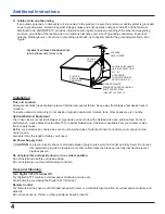
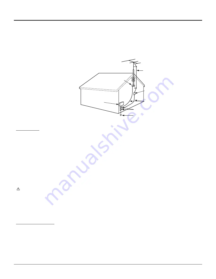
Outdoor Antenna Grounding
If an outside antenna or cable system is connected to the product, be sure the antenna or cable system is grounded
so as to provide some protection against voltage surges and built-up static charges. Article 810 of the National
Electrical Code, ANSI/NFPA 70, provides information with regard to proper grounding of the mast and supporting
structure, grounding of the lead-in wire to an antenna discharge unit, size of grounding conductors, location of
antenna-discharge unit, connection to grounding electrodes, and requirements for the grounding electrode. See
Figure.

Installation

This unit Location
Adequate ventilation is essential to prevent internal component failure. Keep away from areas of excessive heat or
moisture.
To insure optimum color purity do not position magnetic equipment (motors, fans, other speakers, etc.) nearby.

Optional External Equipment
The Video / Audio connection between components can be made with shielded video and audio cables. For best
performance, video cables should utilize 75 

 coaxial shielded wire. Cables are available from your dealer or elec-

tronic supply house.
Before you purchase any cables, be sure you know what type of output and input connectors your various compo-
nents require.
Also determine the length of cable you’ll need.

AC Power Supply Cord

    CAUTION: To prevent electric shock, match wide blade of plug to wide slot of AC outlet and fully insert. Do not use

this (polarized) plug with a receptacle or other outlet unless the blade can be fully inserted to prevent
blade exposure.

Do not place this unit upside down or in a vertical position.
Do not install and use this unit upside down.
Do not install and use this unit standing on its side.

Care and Cleaning

Turn Digital CATV Terminal Off
For Digital CATV Terminal, avoid excessive moisture and wipe dry.
Avoid bumping or scraping the Digital CATV Terminal.

Remote Control
For Remote Control, use a soft cloth dampened with water or a mild detergent solution. Avoid excessive moisture and
wipe dry.
Do not use benzene, thinner or other petroleum based products.

EXAMPLE OF ANTENNA GROUNDING AS PER

(NEC) NATIONAL ELECTRICAL CODE

ELECTRIC
SERVICE
EQUIPMENT

GROUND
CLAMP

ANTENNA
LEAD-IN WIRE

ANTENNA DISCHARGE
UNIT (NEC SELECTION
810 - 20)

GROUNDING
CONDUCTORS (NEC
SELECTION 810 - 21)

GROUND CLAMPS

POWER SERVICE GROUNDING
ELECTRODE SYSTEM
 (NEC ART 250,PART H)

Summary of Contents for TZ-PCD2000

Page 1: ...nstructions Model No TZ PCD2000 For assistance please call your regional operator installer Before connecting operating or adjusting this product please read these instructions completely Save this manual for future reference TQB2AA0369 ...

Page 2: ...lug has two blades with one wider than the other A grounding type plug has two blades and a third grounding prong The wide blade or the third prong are provided for your safety If the provided plug does not fit into your outlet consult an electrician for replacement of the obsolete outlet 10 Protect the power cord from being walked on or pinched particularly at plugs convenience receptacles and th...

Page 3: ...lacement parts specified by the manufacturer Unauthorized substitutions may result in fire electric shock or other hazards l Safety Check Upon completion of any service or repairs to this product ask the service technician to perform safety checks to determine that the product is in proper operating condition l Damage Requiring Service Unplug this product from the wall outlet and refer servicing t...

Page 4: ...vailable from your dealer or elec tronic supply house Before you purchase any cables be sure you know what type of output and input connectors your various compo nents require Also determine the length of cable you ll need AC Power Supply Cord CAUTION To prevent electric shock match wide blade of plug to wide slot of AC outlet and fully insert Do not use this polarized plug with a receptacle or ot...

Page 5: ...gital CATV Terminal with respect to the radio or television equipment that is receiving interference lMove the Digital CATV Terminal away from equipment receiving interference lPlug the Digital CATV Terminal into a different wall outlet so the Digital CATV Terminal and equipment receiving the interference are on different branch circuits If these measures do not eliminate interference please consu...

Page 6: ...structions 2 FCC STATEMENT 5 Installation 7 ACCESSORIES 7 Remote Control battery installation 7 Front and Rear View of the Digital CATV Terminal 8 Cable connection 10 Digital CATV Terminal connection to stereo TV and stereo VCR 10 Digital CATV Terminal connection to TV and VCR 11 Digital CATV Terminal connection to component with Digital Audio Input jack 12 Connect AC Power Cord 12 Power ON OFF 13...

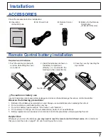
Page 7: ...rrect installation can cause battery leakage and corrosion that will damage the remote control transmitter Observe the following precautions 1 Batteries should always be replaced as a pair Always use new batteries when replacing the old set 2 Do not combine a used battery with a new one 3 Do not mix battery types example Zinc Carbon with Alkaline 4 Do not attempt to charge short circuit disassembl...

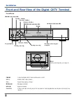
Page 8: ...ory use only Channel Button Factory use only Remote control signal receptor Door Pull the door toward you to open it Card Slot POWER Turns the Digital CATV Terminal Power On or Off VOL Select Volume Up or Down CH Select Channel Up or Down MESSAGE Message indicator BYPASS Bypass indicator Card Slot This is currently not being used It is reserved for future applications as the place for cards to be ...

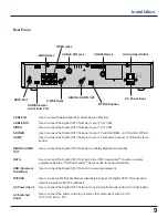
Page 9: ...erminal to your TV with S VIDEO or VCR with S VIDEO Use to connect the Digital CATV Terminal to your TV with stereo sound or VCR with stereo sound Use to connect the Digital CATV Terminal to a Dolby Digital AC 3 decoder Use to connect the Digital CATV Terminal to the VCR CommanderTM module or similar equipment See the VCR CommanderTM User s Guide for more information Use to connect the Digital CAT...

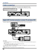
Page 10: ... Connect S VIDEO Cable from the S VIDEO output jack on the Digital CATV Terminal to the S VIDEO input jack on the TV or S VCR Note Connect either the S VIDEO or video input output as shown above l S VIDEO will provide better picture quallity 2 Connect audio cables from the left and right audio output jacks on the Digital CATV Terminal to the left and right audio input jacks on the TV or VCR S VCR ...

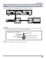
Page 11: ...gital CATV Terminal to the ANT IN jack of the VCR and connect the ANT OUT jack of the VCR to the ANT IN jack of the TV using 75 Ω shielded cable Connecting a non cable ready TV VHF Matching Transformer Jumper Cable TV Set VHF Antenna Terminals Rear of Non Cable Ready TV TV Set UHF Antenna Terminals Note l Additional equipment and cables shown are not supplied with this set VCR or S VCR TV ...

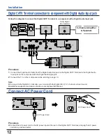
Page 12: ...mponent with the Digital Audio Input jack 2 Connect the TV or other component while referring to page 10 Note l If using a Dolby Digital AC 3 decoder you can enjoy Dolby Digital AC 3 5 1 channel surround sound l Additional equipment and cables shown are not supplied with this set Connect AC Power Cord Procedure l Connect the AC power cord to the AC power input at the rear of the Digital CATV Termi...

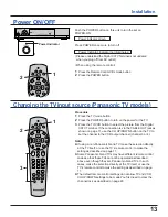
Page 13: ...nnection is via the CABLE OUT jack as shown on page 11 use the CH UP DOWN button on the TV to set the channel to the VCR output channel channel 3 or 4 Note l If using a non Panasonic brand TV make the selection directly at the TV itself or use the TV s remote control to make the setting as described on page 17 l Some Panasonic brand TVs may have different remote control codes so that these TVs can...

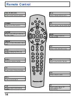
Page 14: ... A B C On Screen decision buttons CH Press to select channel Up Down Mute Press to turn sound off Last Press to return to last channel viewed Menu Press to display Settings menu Info Press to display channel information Exit Press to hide interactive screen Fav Press to view favorite channels VOL Press to adjust volume Guide Press to display interactive program guide 0 9 Press to enter channel and...

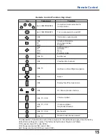
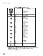
Page 15: ...ight navigation Select Display Next Previous screen On Screen decision buttons Volume up down Channel up down Skip forward rewind Mute audio The description of functions for each of the components in the table above apply when the factory default code settings are in place The factory default code settings are as follows TV Panasonic brand TV code 0250 VCR Panasonic brand VCR code 1062 AUX Panason...

Page 16: ...R Panasonic brand VCR code 1062 AUX Panasonic brand CD Player code 0303 VCR AUX CBL TV VCR AUX CBL TV VCR AUX CBL TV VCR AUX CBL TV VCR CBL TV VCR AUX CBL TV VCR AUX CBL TV VCR AUX ALL COMPONENTS Channel enter Disc VOD rewind Punch to VCR Rewind Fast search rev VOD play Punch to VCR Play Play VOD fast fwd Punch to VCR Fast forward Fast search fwd VOD record Punch to VCR record VOD stop Punch to VC...

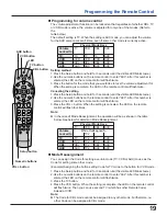
Page 17: ...ment from the factory the code is set to Panasonic brand VCRs code 1062 Use the following procedure to program the VCR or DVD player remote control code 1 Select the Setup Code for your VCR by referring to the tables on pages 21 to 24 If you cannot find the right Setup Code refer to Programming Without Code on page 18 2 Press the VCR button and then press the Setup button and hold for 3 seconds un...

Page 18: ...X for the component that you would like to find out the Code for and then press the Setup button and hold for 3 seconds until the visible LED blinks twice 2 Use the numeric buttons on the remote control to enter 990 After this number is entered the LED on the remote control will flash twice 3 When a 1 is then entered using the numeric buttons the remote control LED will flash The number of times i...

Page 19: ...d the LED on the remote control will flash four times Note l In the case of Mode Reassignment the operation will be as shown in the table below See below for details on Mode Reassignment n Mode Reassignment You can assign the Code for setting a certain mode TV VCR or AUX to use as the Code for setting some other mode Example Assigning the button setting Code for TV mode to the button for VCR mode ...

Page 20: ... Use the numeric buttons on the remote control to enter 973 After this number is entered the LED on the remote control will flash twice 3 Press the CH button When programming is complete the LED on the remote control will flash twice Setting the lock 1 Press the Setup button and hold for 3 seconds until the visible LED blinks twice 2 Use the numeric buttons on the remote control to enter 973 After...

Page 21: ...py 0180 0179 Hallmark 0178 Harley Davidson 0179 Harman Kardon 0054 Harvard 0180 Hitachi 0056 0145 0016 0151 Infinity 0054 Inteq 0017 JBL 0054 JCB 0000 JVC 0053 KEC 0180 KTV 0180 0030 0039 Kenwood 0030 0019 LG 0056 LXI 0047 0054 0154 0156 0178 Logik 0016 Luxman 0056 MGA 0150 0030 0178 0019 MTC 0060 0030 0056 0019 Magnavox 0054 1254 0030 0179 Majestic 0016 Marantz 0054 0030 Matsushita 0250 Megatron ...

Page 22: ...ctrophonic 0037 Emerex 0032 Emerson 0037 0184 0000 0121 0043 0209 0002 0278 Fisher 0047 0104 Fuji 0035 0033 Funai 0000 GE 0035 0060 0048 0240 Garrard 0000 Go Video 0526 GoldStar 0037 Gradiente 0000 HI Q 0047 Harley Davidson 0000 Harman Kardon 0081 Harwood 0072 Headquarter 0046 Hitachi 0000 0042 0041 Hughes Network Systems 0042 JVC 0067 0041 Jensen 0041 KEC 0037 0278 KLH 0072 Kenwood 0067 0041 Koda...

Page 23: ...rantz 0539 Mitsubishi 0521 Onkyo 0503 Optimus 0571 Panasonic 0490 Philips 0503 0539 Pioneer 0525 0571 Proscan 0522 RCA 0522 Samsung 0573 Sony 0533 Technics 0490 Theta Digital 0571 Toshiba 0503 Yamaha 0490 0545 Zenith 0503 Codes for Home Automation for AUX mode Manufacturer List Manufacturer Set Up No Manufacturer Set Up No LiteTouch 0084 Lutron 0597 One For All 0167 Sanyo 0336 Security System 0167...

Page 24: ... 0074 Wards 0158 0014 0189 0080 0054 Yamaha 0176 0186 Yorx 0195 Zenith 0857 Codes for CD Players for AUX mode Manufacturer List Manufacturer Set Up No Manufacturer Set Up No ADC 0018 Adcom 0155 Aiwa 0157 0124 Audio Technica 0170 Burmester 0420 California Audio Labs 0029 0303 Carver 0157 0179 0437 DKK 0000 Denon 0003 Emerson 0305 0164 0155 0469 Fisher 0179 0174 0342 GE 0009 Garrard 0420 0393 0280 G...

Page 25: ...d l Make sure the TV power is turned on l If your setup includes a VCR and or stereo make sure you have properly connected them to the Digital CATV Terminal unit l Make sure your TV is tuned to the proper output channel 3 or 4 l Make sure the volume is turned up l Make sure the RF Bypass is disabled l Make sure the TV is not in MUTE mode l Make sure all cables are properly connected l Adjust the T...

Page 26: ...ni DIN 4 pin Y 1 Vp p 75 Ω C 0 286 Vp p 75 Ω AUDIO OUT RCA pin jack 2 L R 0 5 Vrms DIGITAL AUDIO OUT AC 3 RCA pin jack AC 3 PCM BYPASS For Bypass Module optional accessory DATA For VCR CommanderTM Module optional accessory USB Use to connect the Digital CATV Terminal to external equipment AC Switched Outlet 120 V AC 60 Hz 5 A 14 17 360 mm 2 78 70 5 mm 10 55 268 mm 5 5 lb 2 5 kg Note Design and Spe...

Page 27: ...27 Notes ...
Page 28: ... this book plus your purchase receipt as a permanent record of your purchase to aid in identification in the event of theft or loss and for Warranty Service purposes Model Number TZ PCD2000 Serial Number Panasonic Consumer Electronics Company Division of Matsushita Electric Corporation of America One Panasonic Way Secaucus New Jersey 07094 TQB2AA0369 Printed in USA S0701 0A ...

Reviews: