background image

7

Engine Cylinder Head Inspection and Replacement Procedure

1.  Required parts and tools used

Part names and tools used

Remarks

Sparkplug wrench

Width across 

À

 at: 16 mm

Valve spring replacer

Nissan special tool

Gasket stripper spray

Nihon Kohzai NX66 or equivalent

Scraper

1

Rubber stopper
Sponge

As needed

Thickness gauge

1

Straight edge

1

Binding band (clamper)

As needed

Timing light

1 set

Cylinder head bonding and gasket kit

623-200-1815

Torque wrench

11.8N·m

44.1N·m

88.2N·m

Engine oil

Small amount of Sanyo genuine AP. GHP D -125
Small amount of Sanyo genuine GHP Oil 10TH
Small amount of Sanyo genuine GHP Oil 10W30C2

Socket wrench set

1 set

Extension bar

Approx. 75, 150 mm long

Stem seal insertion tool

1 set

General tools

1 set

2.  Preparation for work

(1) If coolant temperature is high, lower it.

See “Coolant Inspection, Replenishment, and Replacement Procedure” in this manual for coolant pump operation
and stopping method.

(2) See “1. Safety Precautions” and “2. Preparation for work” of “Basic Operation” in this manual.

3. Coolant discharge

For details about the coolant discharge procedure, see “Coolant Inspection, Replenishment, and Coolant Replacement
Procedure.”

GHP̲Main̲Parts̲Replacement.indd   7

2012/07/31   17:54:17

Summary of Contents for U-16GE2E5

Page 1: ...pplicable Models 2WAY MULTI W MULTI U 16GE2E5 U 16GEP2E5 U 20GE2E5 U 20GEP2E5 U 25GE2E5 U 25GEP2E5 U 30GE2E5 3WAY MULTI U 16GF2E5 U 20GF2E5 U 25GF2E5 Reference No SM7110038 01 Main Parts Replacement July 2012 Order No SM7110038 11CE ...

Page 2: ...e 7 4 Disconnect all lead wires 8 5 Disconnect all hoses 9 6 Remove exhaust gas heat exchanger 11 7 Remove intake manifold and exhaust manifold 11 8 Remove rocker cover 12 9 Remove ignition coils 12 10 Remove ignition coil bracket 12 11 Remove spark plugs 13 12 Remove cylinder head assembly 13 13 Strip and clean gasket Figure18 14 14 Attach cylinder head 15 15 Valve clearance adjustment procedure ...

Page 3: ...tart test operation and set engine rotational speed 26 4 Ignition timing check 27 5 Correction for distorted amount 28 6 Cancel settings 31 7 Stop test run 32 8 Final check 32 Front Oil Seal Replacement Procedure 1 Required parts and tools used 33 2 Preparation for work 33 3 Remove compressor drive belt 33 4 Remove the crank pulley 33 5 Remove front cover oil seal Figure 2 33 6 Install the front c...

Page 4: ...t Procedure 1 Required parts and tools used 42 2 Prepare to remove the expansion valve liquid valve bypass valve and waste heat recovery valve 42 3 Preparation for work 42 4 Prepare to remove the expansion valve liquid valve bypass valve and waste heat recovery valve 43 5 Install the expansion valve liquid valve bypass valve and waste heat recovery valve 44 6 Preparation for operation 44 7 Final c...

Page 5: ...68 Pump Down Procedure Common to Cooling and Heating 1 Select the pump down mode 69 2 Stop operation for all indoor units 69 3 Remove refrigerant shutoff valve cap 69 4 Attach the gauge manifold 69 5 Operating the refrigerant shutoff valve 3 WAY MULTI only 71 6 Start the test run Carry out a test run on the outdoor unit 72 7 Con gure the forced close setting of the bypass valve 73 8 Set engine rot...

Page 6: ...ools used 83 2 Preparation for work 83 3 Mixer cleaning procedure 83 4 Preparation for operation 83 5 Final check 83 Reference Document Refrigerant Coolant Fuel Air Supply and Exhaust and Engine Oil Filling System 84 Bolt Tightening Torque Table 86 ...

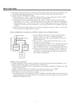
Page 7: ...e carrying out the backup operation close the closing valves of all outdoor units for which the stop operation has been performed 2 Models other than W MULTI Safety Precautions Stopping only the indoor unit is extremely dangerous because the engine may suddenly start if the customer operates the remote controller on the indoor unit side Before carrying out work on the inside of the outdoor unit ma...

Page 8: ...rmed for all outdoor units an outdoor unit cannot be started even with a command of the indoor unit g After 3 minutes has elapsed since the display of the ݙݖ ܞݕ indication in the seven segment LED display of Figure 2 the ݘݕܞݕ indication in the seven segment LED display of Figure 3 is displayed h Turn off the power supply circuit breaker for the outdoor unit Models other than W MULTI c Turn off the...

Page 9: ...cedure To perform backup operation the outdoor unit for maintenance work hereafter referred to as target outdoor unit must be cut off from the system using the following procedure Review content of the maintenance work and then select the most suitable method Also after the maintenance work is nished always refer to System recovery procedure and then return the system to its normal state Backup op...

Page 10: ...the W MULTI outdoor unit 2 indicated in the left diagram perform Step 1 to Step 3 in Backup operation procedure in that order Then perform maintenance work on W MULTI outdoor unit 2 b When Step 3 is nished W MULTI outdoor unit 1 is reset It ll stop even if it is operating c After approximately ve minutes if there is operation input indoor remote controller is Run or test run setting on outdoor mai...

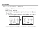
Page 11: ...topper Do not try to rotate it any further The valve is fully closed when the slit of the tab is at right angles to the pipe and fully open when the slit of the tab is parallel to the tube Fully closed Refrigerant gas tube Refrigerant liquid tube Refrigerant gas tube Refrigerant liquid tube Fully opened Note 1 If the unit is operated while the closing valves are still closed the discharge pressure...

Page 12: ...quid tube The valve is fully open when the tab has been rotated 90 degrees when it contacts the stopper Do not try to rotate it any further The valve is fully closed when the slit of the tab is at right angles to the pipe and fully open when the slit of the tab is parallel to the pipe Fully closed Fully opened Refrigerant suction tube Balance tube Refrigerant discharge tube Refrigerant suction tub...

Page 13: ... m Engine oil Small amount of Sanyo genuine AP GHP D 125 Small amount of Sanyo genuine GHP Oil 10TH Small amount of Sanyo genuine GHP Oil 10W30C2 Socket wrench set 1 set Extension bar Approx 75 150 mm long Stem seal insertion tool 1 set General tools 1 set 2 Preparation for work 1 If coolant temperature is high lower it See Coolant Inspection Replenishment and Replacement Procedure in this manual ...

Page 14: ...e the stepping motor connector white 6P and the fuel adjustment valve connector red 6P 4 Move the lead wires to the right so that they do not interfere with subsequent work Figure 1 Ignition coil connectors Figure 1 Ignition coil connectors Figure 2 Coolant temperature sensor connector Figure 2 Coolant temperature sensor connector Figure 3 Fuel gas adjustment valve Stepping motor Figure 3 Fuel gas...

Page 15: ... 5 6 Exhaust hose from exhaust gas heat exchanger to mufÀer Figure 5 7 Coolant hose engine inlet side Figure 6 Figure 4 Blow by hose Equalizer hose Coolant hose Engine outlet Figure 4 Blow by hose Equalizer hose Coolant hose Engine outlet Figure 5 Coolant hose from exhaust gas heat exchanger to engine Coolant hose from coolant pump to exhaust gas heat exchanger Exhaust hose from exhaust gas heat e...

Page 16: ...oss Àat 7 mm 9 Intake hose mixer side Figure 7 Hose Clamp width across Àat 7 mm 10 Intake hose air cleaner side Figure 8 Hose Clamp width across Àat 7 mm Figure 7 Fuel gas hose Air intake hose Figure 7 Fuel gas hose Air intake hose Figure 8 Intake hose air cleaner side Figure 8 Intake hose air cleaner side ...

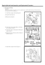
Page 17: ...s Àat 17 mm Nut width across Àat 12 mm 7 Remove intake manifold and exhaust manifold Remove 10 bolts and nuts indicated by arrows in Figure 11 and remove with mixer and stepping motor still attached to intake manifold Bolt nut width across Àat 14 mm Ɣ After removing the intake manifold remove the exhaust manifold Figure 9 Nuts Figure 9 Nuts Figure 10 Nuts Bolts Hexagon socket head bolt Figure 10 N...

Page 18: ...n Figure 13 Bolt width across Àat 10 mm Caution Handle the ignition coils carefully Keep them free from shock 10 Remove ignition coil bracket 1 Remove 2 securing bolts indicated by Figure 14 remove ignition coil bracket Bolt securing the bracket width across Àat 12 mm Figure 12 Cap nut Seal washer Cap nuts Figure 12 Cap nut Seal washer Cap nuts Figure 13 Ignition coils Ignition coil retaining bolt...

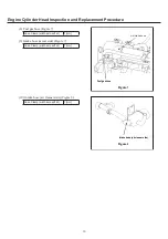
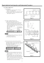
Page 19: ...n in Figure 16 before loosening the bolts reassembly will become easier Ɣ Remove the cylinder head bolts Ɣ Remove the cylinder head gasket Caution To prevent distortion of the cylinder head when loosening the cylinder head bolts loosen them gradually in the order shown in Figure 17 Bolt width across Àat 14 mm Figure 15 Figure 15 Figure 16 Valve rocker bolt Screw Adjustment nut Compress and tie the...

Page 20: ...ve carbon and sludge adhering inside circulation channels 5 Clean each circulation hole in the cylinder head by blowing with compressed air 6 Strip gasket material from and clean both the attachment areas for the intake manifold exhaust manifold and the exhaust gas heat exchanger using the same procedure as described for the cylinder head above Caution 1 Make absolutely sure no foreign matter fall...

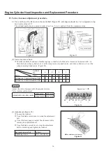
Page 21: ... of the cylinders and each of the intake and exhaust in the positions where they were before disassembly Figure 21 Ɣ The pushrods must be correctly seated in the depression for them on the valve lifter Ɣ Assemble the rocker shaft assembly Bolt width across Àat 12 mm Tightening torque 19 6 23 5 N m Caution Ɣ Tighten each bolt securing the rocker shaft to the speci ed torque evenly in three stages g...

Page 22: ...der no 4 is at the compression top dead centre Figure 24 Cylinder No 4 3 2 1 Status Valve Ex In In Ex Ex In In Ex Cylinder no 1 at compression TDC Cylinder no 4 at compression TDC Caution Adjust the valve clearance while the engine is warm Valve clearance adjustment Adjustment value when warm Intake valve 0 45 mm Exhaust valve 0 45 mm 3 Adjustment Figure 25 c Loosen the locknut d Use a Àat blade s...

Page 23: ...e insulator 5 If the tip of the centre electrode is rounded as shown in c of Figure 28 replace the plug with a new one 6 If the ground electrode is worn as shown in d of Figure 28 replace the plug with a new one 7 Check the electrode gap of the sparkplug Reference value 0 4 0 5 mm Caution c Do not adjust the gap because an iridium chip is used d Do not insert a thickness gauge between the electrod...

Page 24: ... 20 Install intake manifold and exhaust manifold Install the intake manifold and exhaust manifold by tightening the 10 bolts and nuts indicated by the arrows in Figure 32 use a new gasket Bolt nut width across Àat 14 mm Bolt 2 tightening torque 32 4 38 2 N m Flange nut 4 tightening torque 41 2 48 1 N m Nut Àangeless 4 tightening torque 32 4 38 2 N m Ɣ After installing the exhaust manifold install ...

Page 25: ...nger installation by tightening the 6 bolts indicated by arrows in Figure 34 Bolt nut width across Àat 17 mm Tightening torque 37 3 44 1 N m 22 Reconnect all hoses Securely connect all hoses and parts and install and tighten hose bands so that no leakage occurs 23 Connect all lead wires Check the pins of the connecting parts to make sure none of them are loose or missing 24 Install other parts Ins...

Page 26: ... Coolant Inspection Replenishment and Replacement Procedure in this manual 27 Final check 1 Running condition check c Make sure that no abnormal noise or vibration occurs d Make sure there are no coolant or oil leaks e Make sure that none of the attached parts are loose 2 Cleanliness check of the surroundings c Make sure no unneeded items or trash is scattered around d Make sure no tools etc have ...

Page 27: ... width across Àat 14 mm 4 Install starter The starter installation procedure is the reverse of the removal procedure 1 Install the starter by tightening the bolts in Figure 2 that secure the starter Tightening torque 32 4 38 2 N m 2 Reconnect the wires for the B and S terminal connectors on the starter as shown in Figure 1 Tightening torque 9 8 11 8 N m 5 Preparation for operation 1 Turn on the po...

Page 28: ...ng installation Ɣ Handle the ignition coils carefully Keep them free from shock Bolt width across Àat 10 mm Tightening torque 6 4 7 5 N m 4 Crank angle sensor Figure 2 1 Crank angle sensor removal and installation c Remove the harness connector d Remove the crank angle sensor 2 Points to keep in mind during installation c Coat the O ring with engine oil during installation d Make sure that there a...

Page 29: ... 16 mm 3 If the tip of the plug is completely black with dry carbon the mixture may be too rich the ignition timing may be retarded or oil may be going up and down within the cylinder Investigate these possibilities 4 If the tip of the plug is black and moist the air cleaner element may be clogged Investigate this possibility 5 If the insulator at the tip of the plug is burned completely white and...

Page 30: ...m Tightening torque 20 0 29 0 N m 14 Install ignition coils Install the ignition coils by tightening the bolts that secure them indicated by arrows in Figure 8 Bolt width across Àat 10 mm Tightening torque 6 37 7 45 N m Caution Handle the ignition coils carefully Keep them free from shock 7 Preparation for operation 1 Turn on the power supply circuit breaker for the outdoor unit 2 Open the main ga...

Page 31: ...nd or more Menu item number ע ע Figure 1 will be displayed 2 Press the UP S005 or DOWN S006 key displaying the menu item numbers Select menu item ע צ in the Figure 2 The display ؠ Figure 3 will appear Figure 3 Figure 2 3 Press the SET key S007 Figure 4 will bedisplayed The LEVEL LED D053 will be illuminated 4 Press the UP S005 or DOWN S006 key to display ؠ Figure 5 Press the SET key S007 for one s...

Page 32: ...ؠ Figure 8 will appear Figure 8 Figure 7 3 Press the SET key S007 Figure 9 will be displayed The LEVEL LED D053 will be illuminated Press the SET key S007 for one second or more The TEST WARNING LED D052 will be illuminated and the test run will start Set the engine rotational speed to 800 min 1 4 Press the HOME key S004 for one second or more Menu item number ע ע Figure 10 will be displayed 5 Pre...

Page 33: ...governed by the engine in units of 100 revolutions 4 Ignition timing check When the operation conditions stabilize select ע ע operation data display and display ר ע engine ignition timing Check that this value is the value shown in table 1 1 Press the HOME S004 key for one second or more Menu item number ע ע Figure 13 will be displayed The TEST WARNING LED D052 will be illuminated After that ף ף פ...

Page 34: ... S004 for one second or more Menu item number ע ע Figure 15 will be displayed 2 Press the UP S005 or DOWN S006 key displaying the menu item numbers Select menu item ע ק in the Figure 16 The display ؠ Figure 17 will appear Figure 17 Figure 16 3 In this state press the SET key S007 The display will change to ע ע ע Figure 18 and the LEVEL LED D053 will be illuminated 4 Next press the UP S005 or DOWN ...

Page 35: ...ated and LEVEL LED D053 will Àash 3 Press the UP S005 or DOWN S006 key to set a correction of 2 in relation to the current value checked in 1 The display will show ת ת פ Figure 20 Caution The display example at right is an example for when the current value checked in 1 is zero 0 If the current value is 1 and a 2 correction is set in relation to that value the value will become 3 after the setting...

Page 36: ... LED D053 will Àash 3 Press the UP S005 or DOWN S006 key to set a correction of 3 in relation to the current value checked in 1 The display will show ת ת ؘ ץ Figure 23 Caution The display example at right is an example for when the current value checked in 1 is zero 0 If the current value is 2 and a 3 correction is set in relation to that value the value will become 1 after the setting is made The...

Page 37: ...peed will be displayed at one second intervals as shown below Display Item ף ף צ ע ע 10 1400 Forced engine rotational speed example 1400 min 1 ף ף צ ע ע 11 1400 Engine rotational speed example 1400 min 1 ף ק ר 12 0 56 Compressor inlet pressure Example 0 56MPa ף ׯ ק ר 13 0 56 Compressor outlet pressure Example 0 56MPa ף ױ ת ױ ר 15 85 0 Compressor outlet temperature Example 85 0 C 4 Press the SET ke...

Page 38: ... be displayed 2 Press the UP S005 or DOWN S006 key displaying the menu item numbers Select menu item ע צ in the Figure 34 The display ؠ Figure 35 will appear Figure 35 Figure 34 3 Press the SET key S007 Figure 36 will be displayed The LEVEL LED D053 and TEST WARNING LED D052 will be illuminated 4 Press the SET key S007 for one second or more The TEST WARNING LED D052 will go out and the test run w...

Page 39: ...ompressor Replacement Procedure in this manual for instructions on removing the compressor drive belt 4 Remove the crank pulley Remove the 8 bolts indicated by arrows in Figure 1 and remove the crank pulley Bolt width across Àat 12 mm 5 Remove front cover oil seal Figure 2 1 Use a Àat blade screw driver or the like to make a groove in the front cover oil seal 2 Insert needle nose pliers or the lik...

Page 40: ...p of the crank pulley is aligned with the timing pin on the front cover Bolt width across Àat 12 mm Tightening torque 19 6 N m Caution The pitch is different only for the hole marked with a Reference Use a ratchet or the like in the crank pulley hole Figure 4 to turn the crank pulley Do not use any other part to forcibly turn the pulley 8 Install the compressor drive belt For details on the proced...

Page 41: ...s d Make sure there are no oil leaks e Make sure that none of the attached parts are loose 2 Cleanliness check of the surroundings c Make sure no unneeded items or trash is scattered around d Make sure no tools etc have been forgotten within the unit e Use rags to wipe up any water or oil that has accumulated in the bottom of the unit ...

Page 42: ... supporting the socket on the socket wrench with a hand Figure 2 Bolt width across Àat 19 mm Caution To prevent the Àywheel from falling out when removing the Àywheel bolts leave two of the bolts in a state in which two or three turns is still required to remove them 3 Insert Àat blade screwdrivers to the right and left of the Àywheel and remove the Àywheel from the crankshaft housing while twisti...

Page 43: ...ightening torque 137 3 N m Caution Do not forget to remove the Àywheel stopper 6 Preparation for operation 1 Turn on the power supply circuit breaker for the outdoor unit 2 Open the main gas valve starting the fuel supply 3 Set the STOP SW S001 from STOP to NORM Figure 6 7 Final check 1 Running condition check c Make sure that no abnormal noise or vibration occurs d Make sure there are no oil leak...

Page 44: ...nect the fuel gas pipe Remove the hose band from the fuel gas hose and disconnect the hose Remove bolt B 1 and hexagon socket head bolts C 2 places and remove the fuel gas solenoid valve and zero governor integral part Figure 2 Bolt B width across Àat 10 mm Hexagon socket head bolt C width across Àat 4 mm Hose band width across Àat 7 mm Figure 2 Zero governor Hose clamp Fuel gas solenoid valve Hos...

Page 45: ... the outdoor unit 2 Open the main gas valve starting the fuel supply 3 Set the STOP SW S001 from STOP to NORM Figure 3 8 Final check 1 Running condition check c Make sure that no abnormal noise or vibration occurs d Make sure there are no gas leaks e Make sure that none of the attached parts are loose 2 Cleanliness check of the surroundings c Make sure no unneeded items or trash is scattered aroun...

Page 46: ...he wire connectors from the three way valve 2 Remove the hose clamp from the three way valve and separate the hose from the valve 3 Remove the securing bolts and remove the three way valve and its securing bracket 4 Remove the securing bracket from the three way valve 5 Install the three way valve 1 Installation procedure is the reverse of the removal procedure Caution After you connect the wires ...

Page 47: ...bration occurs d Make sure there are no coolant leaks e Make sure there is no looseness in any parts attachment area 2 Cleanliness check of the surroundings c Make sure no unneeded items or trash is scattered around d Make sure no tools etc have been forgotten within the unit e Use rags to wipe up the water or oil that has accumulated at the bottom inside the unit ...

Page 48: ... 1981 Bypass valve 623 165 7105 Welding apparatus 1 set Clamp As needed General tools 1 set 2 Prepare to remove the expansion valve liquid valve bypass valve and waste heat recovery valve 1 Perform the pump down procedure to recover the refrigerant from within the compressor and unit and move it to the indoor unit For details on the pump down procedure see Pump Down Procedure Common for Cooling an...

Page 49: ...e the unit 4 Use a welder Àame to heat the welded joints of the pipes at the locations indicated by the arrows in Figures 1 to 3 and then remove the expansion valve liquid valve bypass valve and waste heat recovery valve When soldering be sure to replace with nitrogen gas Figure1 1 Models 45 0 to 71 0KW Type except 3WAY Waste heat recovery valve Expansion valve Liquid valve Bypass valve Figure 1 3...

Page 50: ... Purge the refrigeration circuit Degree of vacuum 0 133 kPa abs 1 0 mmHg Set to valve open and carry out evacuation from the low pressure outlet After evacuation is nished cancel the valve open setting 6 Preparation for operation 1 Cancel pump down Set each of the closing valves from the fully closed position to the fully open position Figures 2 3 Outdoor unit Refrigerant liquid tube Refrigerant g...

Page 51: ...P side to the NORM side Figure 4 7 Final check 1 Running condition check c Make sure that no abnormal noise or vibration occurs d Make sure there are no refrigerant leaks e Make sure that none of the attached parts are loose 2 Cleanliness check of the surroundings c Make sure no unneeded items or trash is scattered around d Make sure no tools etc have been forgotten within the unit e Wipe up any w...

Page 52: ...tting c Press the HOME key S004 for one second or more Menu item number ע ע Figure 1 will be displayed d Press the UP S005 or DOWN S006 key displaying the menu item numbers Select menu item ע ק in the Figure 2 The display ؠ Figure 3 will appear Figure 3 Figure 2 e In this state press the SET key S007 The display will change to ע ע ע Figure 4 and the LEVEL LED D053 will light f Press the UP S005 ke...

Page 53: ...the Àare portions Figure 6 3 Install pressure sensor 1 Install a new pressure sensor Always use 2 wrenches when tightening the Àare portions Tightening torque 15 20 N m Caution Make sure the connector on the sensor is facing the rear of the unit when installing 2 Other installation procedures are the reverse of the removal procedures 3 Perform an air tightness test with nitrogen from the low press...

Page 54: ...7 Open Closed Refrigerant liquid tube Refrigerant gas tube Refrigerant liquid tube Refrigerant gas tube Note For details on 3WAY multi valves refer to 5 Basic Operation for Shutoff Valves of 3 WAY MULTI under Basic Operations in this manual 6 Remove the gauge manifold 7 Turn on the power supply circuit breaker for the outdoor unit Figure 8 Closed valve open close Fully open Fully closed Status ...

Page 55: ... Press the UP S005 or DOWN S006 key displaying the menu item numbers Select menu item ע ק in the Figure 10 The display ؠ Figure 11 will appear Figure 11 Figure 10 e In this state press the SET key S007 The display will change to ע ע ע Figure 12 and the LEVEL LED D053 will light f Press the UP S005 key or DOWN S006 key to display ؠ ؠ ignore pressure sensor The TEST WARNING LED D052 lights In this s...

Page 56: ...heck c Make sure that no abnormal noise or vibration occurs d Make sure there are no refrigerant leaks e Make sure there is no looseness in any parts attachment area 2 Cleanliness check of the surroundings c Make sure no unneeded items or trash is scattered around d Make sure no tools etc have been forgotten within the unit e Use rags to wipe up the water or oil that has accumulated at the bottom ...

Page 57: ...k Replenishment and Replacement Procedure in this manual 4 Remove the coolant pump 1 Unplug the connector for the coolant pump from the power board in Figure 1 Caution Remove the connector after verifying that the power breaker has been turned off Removing the connector with the power supply still on may lead to damage to the unit ළ ࡐࡦࡊࠦࡀࠢ Power board Figure 1 Connector for coolant pump 2 Remove t...

Page 58: ...it 2 Open the main gas valve starting the fuel supply 3 Set the STOP SW S001 from STOP to NORM Figure 3 7 Fill up with coolant For details of the coolant lling procedure see Coolant Check Replenishment and Replacement Procedure in this manual 8 Final check 1 Running condition check c Make sure that no abnormal noise or vibration occurs d Make sure there are no coolant leaks e Make sure that none o...

Page 59: ...ration in this manual 3 Check and replenish coolant 1 Check and replenish coolant c Check the coolant level inside the reserve tank from the cutout of the side panel on the ller neck side of the unit Figure 1 Suitable Levels Between the L and H levels d If the level within the reserve tank is low replenish the coolant with the speci ed concentration of genuine Panasonic coolant 50 5 up until the H...

Page 60: ...e the end of the hose in a plastic container in order to collect the coolant 4 Open the coolant replenishment port cover and ller neck cap on the top panel to allow air to enter Figure 4 Figure 4 Filler neck cap Coolant Coolant refill hole cover 5 Discharge from the heat exchanger Figure 5 Turn the manual stopcock on the coolant discharge port to Fully opened Figure 5 Coolant discharge port Fully ...

Page 61: ...mount when mixed with water litre Concentrate solution amount litre 45 0 or 56 0 KW Type 24 0 12 0 71 0 KW Type 29 0 14 5 4 Remove the coolant replacement port cover from the top panel 5 Use pinch pliers or the like to pinch the hose from the ller neck to the reserve tank place indicated by the arrow in Figure 7 Protect the hose with a rag or the like to prevent it from being damaged 6 Remove the ...

Page 62: ...matic air purge mode Turn off the remote controllers for all indoor units and stop the operation of the outdoor unit 1 Operation procedures c Press the HOME key S004 for one second or more Menu item number ע Figure 10 will be displayed d Press the UP S005 or DOWN S006 key displaying the menu item numbers Select menu item ע װ Figure 11 The display ؠ will appear Figure 12 Figure 12 Figure 11 e In th...

Page 63: ...rform any manual operations i Replenish the coolant in the coolant replenishment container before it runs out Be careful because if the coolant replenishment container runs out of water air will become mixed with the coolant and the air will be unable to be suf ciently purged Furthermore check the air discharge state with the air purge hose transparent during the automatic airpurge operation j The...

Page 64: ...coolant replenishment port cover Figure 4 7 Wipe up any spilt coolant with a rag and reattach the front panel and rear panel to complete the work procedure 5 Coolant pump operation and stopping procedures Turn off the remote controllers for all indoor units and stop the operation of the outdoor unit 1 Operation procedures c Press the HOME key S004 for one second or more Menu item number ע Figure 1...

Page 65: ...ע Figure 22 will be displayed d Press the UP S005 or DOWN S006 key displaying the menu item numbers Select menu item ע װ Figure 23 The display ؠ will appear Figure 24 Figure 24 Figure 23 e In this state press the SET key S007 The display will change to and the LEVEL LED D053 will be illuminated Figure 25 f Press the UP S005 DOWN S006 key and select menu item ؒ Figure 26 g In this status press the ...

Page 66: ...4 1 N m 77 5 to 90 2 N m General tools 1 set Clamp As needed Socket wrench 1 set 2 Prepare to remove the compressors 1 Perform a pump down and recover all refrigerant from within the compressor and unit and move it to the indoor unit For details about the pump down procedure see Pump Down Procedure heating in this manual Recover any refrigerant that cannot be pumped down 3 Preparation for work 1 S...

Page 67: ...bracket Figure 4 Bolt width across Àat 19 mm f Rotate the tension adjustment bolt until the compressor drive belt can be removed then remove the belt 2 Unplug the crankcase heater sensor and clutch connectors 3 Cut the oil tube clamps 4 Remove the bolts ེ indicated by arrows in Figure 5 and remove the discharge and suction pipe Àanges Bolt width across Àat 10 mm c j Figure 5 Figure 4 ...

Page 68: ... unit s base leave hoses in place Put a block of wood or the like against the edge of the engine s oil pan and jack it up until there is no load on the rubber vibration damper on the compressor Then remove the mounting bracket from under the rubber vibration damper and remove the damper from the engine mount Adjust the height with the jack so no signi cant load is on the rubber vibration damper 10...

Page 69: ...ten each of the bolts nuts in the order of c unit base and mounting bracket ĺ d mounting bracket and vibration damper ĺ e vibration damper and engine mount Once the unit base and mounting bracket bolts are tightened gently rock the engine itself a number of times and make sure there is no signi cant strain on the vibration damper before fastening the vibration damper to the mounting bracket c Unit...

Page 70: ...l provisionally adjust it rotate the centre of the pulley about one turn with a socket wrench and then adjust the tension again Repeat this operation until the tension is adjusted Figure 9 f Tighten the tension adjustment bolt so that the tension of the compressor drive belt measured with a noncontact sonic belt tension meter reaches the speci ed value Belt tension 1670 to 1720N initially 1180 to ...

Page 71: ...arting the fuel supply 4 Set the STOP SW S001 from STOP to NORM Figure 11 7 Final check 1 Running condition check c Make sure that no abnormal noise or vibration occurs d Make sure there are no refrigerant leaks e Make sure that none of the attached parts are loose 2 Cleanliness check of the surroundings c Make sure no unneeded items or trash is scattered around d Make sure no tools etc have been ...

Page 72: ...ions and 2 Preparation for work of Basic Operation in this manual 3 Remove the fan motor 1 Remove the fan guard 2 Use a Àat blade screwdriver to remove the hub cover of the fan 3 Loosen the bolts indicated by circles in Figure 1 and remove the fan 4 Disconnect the connectors for the fan motor from the circuit board indicated by circles in Figure 2 Caution Remove the connecter after verifying that ...

Page 73: ... fan motor to the board in Figure 2 and secure the wires in place 3 Coat the fan securing bolts indicated by circles in Figure 4 with Loctite 272 align the fan with the shaft of the fan motor chamfered on both sides and install the fan Tightening torque 7 8 N m 4 Use a plastic hammer to attach the hub cover of the fan Important Align the protruding portions of the hub cover with the fan bolts circ...

Page 74: ...M side Figure 5 6 Final check 1 Running condition check c Make sure that no abnormal noise or vibration occurs d Make sure there is no looseness in any parts attachment area 2 Cleanliness check of the surroundings c Make sure no unneeded items or trash is scattered around d Make sure no tools etc have been forgotten within the unit e Use rags to wipe up the water or oil that has accumulated at the...

Page 75: ...lowing explanation is for both the cooling mode and heating mode 2 Stop operation for all indoor units Turn off remote controllers for all indoor units The test run settings cannot be con gured from the outdoor main board while the indoor unit is being operated remote controller is on Cooling is not possible during the pump down work and until recovery is complete after the work is nished so make ...

Page 76: ...arge tube and refrigerant suction tube Figure 3 d Heating pump down Connect the gauge manifold to the service port of the refrigerant discharge tube and refrigerant suction tube Close the valve on the manifold gauge Figure 4 Figure 3 Cooling Gauge manifold Refrigerant discharge shutoff valve Refrigerant suction shutoff valve Refrigerant liquid shutoff valve Gauge manifold Refrigerant discharge shu...

Page 77: ...ntake tube Refrigerant liquid tube Refrigerant discharge tube Closed Open Open Close up view Closed valve open close Fully open Fully closed Status Figure 5 2 Heating pump down Fully close the suction shutoff valve Figures 7 and 8 Refrigerant intake tube Refrigerant discharge tube Refrigerant liquid tube Closed Open Open Close up view Closed valve open close Fully open Fully closed Status Figure 8...

Page 78: ...umber ע will be displayed 2 Press the UP S005 DOWN S006 key and select menu item number ע װ Figure 9 The display ؠ Figure 10 will appear 3 Press the SET S007 key Figure 11 will be displayed The LEVEL LED D053 will be illuminated 4 Press the UP S005 key or DOWN S006 key to select the test run mode Cooling mode Figure 11 Heating mode Figure 12 5 Press the SET S007 key for 1 second or more The TEST W...

Page 79: ...t menu item ؠ Figure 13 4 Press the SET S007 key for 1 second or more The TEST WARNING LED D052 will be illuminated and the bypass valve will be set to fully closed Caution This setting results in not just the bypass valve but also the liquid valve outdoor fan and the like performing the operation required for the pump down Be sure to con gure this setting because a pump down may not be possible i...

Page 80: ...d the TEST WARNING LED D052 will be illuminated 5 In this state use the UP S005 key or DOWN S006 key to change the forced engine rotational speed Refer to the following for the number of rotations to set Set RPM 800 to 1 000 min 1 Display Item Forced engine rotational speed example 1 400 min 1 Engine rotational speed example 1 400 min 1 Compressor input pressure example 0 56 MPa Compressor output ...

Page 81: ...t pressure drops the micro computer automatically stops the engine and the pump down is complete If the engine is stopped in this way Figure 19 is displayed on the outdoor main board However if 15 minutes have elapsed since the bypass valve forced close setting explained in item 7 was set the engine stops automatically regardless of the refrigerant pressure In such a case is displayed Caution Even...

Page 82: ...rned off because of conditions on site perform the process to Cancel Each Setting in the next item Figure 21 Figure 20 Caution To protect the equipment carry out the work to stop the outdoor unit after 3 minutes have elapsed since the engine was stopped The process to cool the engine is performed by the coolant water pump outdoor fan and the like immediately after the engine has stopped 13 Cancel ...

Page 83: ... wrench 13 mm and 17 mm 2 Preparation for work 1 See 1 Safety Precautions and 2 Preparation for work of Basic Operation in this manual 3 Remove the generator 1 Remove the front and rear panels from the outdoor unit 2 See Figure 1 Remove bolt c Table 2 Bolt size across Àats 17 mm Loosen bolt d and nut e Table 3 Bolt nut size across Àats 17 mm Loosen bolt f Table 4 Bolt size across Àats 17 mm 3 See ...

Page 84: ...3 Loosen tension adjustment bolt h and nut i Table 6 Bolt nut size across Àats 14 mm 5 See Figure 4 Lift up the generator and remove the belt j 6 See Figure 5 Remove the generator s wiring connector k 3P and connector l 2P Figure 3 Figure 4 Figure 5 ...

Page 85: ...nt Procedure 7 See Figure 6 Remove bolt g 8 See Figure 7 While supporting the generator remove bolt d and the nut washer and spacer e and bolt washer and spacer f nally remove the generator from the machine Figure 6 Figure 7 ...

Page 86: ...50N initially 260 to 310N after 8 hours Doctor Tension Settings Span 295 mm tension measurement position Density 0 018 kg m rib Number of ribs 5 Doctor Tension Tester manufactured by Mitsuboshi Belting Ltd The tester measures tension using the sound that a vibrating belt produces Press your nger against the belt at the tension measurement position and measure the sound from strumming it using the ...

Page 87: ...he tension of belt j again Refer to Table 7 for belt tensions If the belt is not at the speci ed tension redo procedure 2 If both the torques and tension are at speci ed values loosen the tension adjustment bolt h to back it off from the engine and tighten nut i to secure the tension adjustment bolt h Caution Back the tension adjustment bolt h slightly away from the engine as shown in Figure 11 th...

Page 88: ... none of the attached parts are loose 2 Cleanliness check of the surroundings c Make sure no unneeded items or trash is scattered around d Make sure no tools etc have been forgotten within the unit e Use rags to wipe up any water or oil that has accumulated in the bottom of the unit Supplemental Notes Nut Bolt Slip Marker Painting slip markers as shown in Figure 13 onto the bolts and nuts that wer...

Page 89: ...pray carburetor cleaner directly on the mixer because it can cause the deterioration of resin and rubber parts 4 Preparation for operation 1 Turn on the power supply circuit breaker for the outdoor unit 2 Open the main gas valve starting the fuel supply 3 Set the STOP SW S001 from STOP to NORM Figure 1 5 Final check 1 Running condition check c Make sure that no abnormal noise or vibration occurs d...

Page 90: ...84 Reference Document W MULTI Refrigerant Coolant Fuel Air Supply and Exhaust and Engine Oil Filling System ...

Page 91: ...85 Reference Document Refrigerant Coolant Fuel Air Supply and Exhaust and Engine Oil Filling System 3 WAY MULTI ...

Page 92: ... 7 06 1 47 10 3 5 M6 50 90 120 25 4 90 8 83 11 77 2 45 11 M7 90 160 220 45 8 83 15 69 21 57 4 41 13 12 4 6 M8 120 220 290 60 11 77 21 57 28 44 5 88 17 14 5 8 M10 240 430 580 120 23 54 42 17 56 88 11 77 19 17 22 6 10 M12 420 760 1 000 210 41 19 74 53 98 07 20 59 22 19 6 12 M14 690 1 240 1 650 350 67 67 121 60 161 81 34 32 24 22 27 8 14 M16 1 080 2 000 2 600 540 105 91 196 13 254 97 52 96 27 24 8 14...

Reviews: