47
Pressure Sensor Replacement Procedure
(3) Set the gauge manifold into position.
(4) Purge the air in the hose.
(5) Perform the pump-down procedure to recover the
refrigerant from within the unit to the indoor unit
side. For details on the pump-down procedure, see
“Pump Down Procedure (Heating)” in this manual.
To determine the unit pressure, refer to the value of
the gauge manifold.
(6) Preparation for work
c
See “1. Safety Precautions” and “2. Preparation for
Work” of “Basic Operation” in this manual.
(7) Unplug the pressure sensor connector.
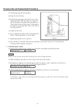
(8) Use wrenches to disconnect the pressure sensor
À
are connections. Always use 2 wrenches when
loosening the
À
are portions. (Figure 6)
3. Install pressure sensor
(1) Install a new pressure sensor. Always use 2 wrenches when tightening the
À
are portions.
Tightening torque
15 ~ 20 [N·m]
Caution
Make sure the connector on the sensor is facing the rear of the unit when installing.
(2) Other installation procedures are the reverse of the removal procedures.
(3) Perform an air tightness test with nitrogen from the low pressure outlet, and make sure there are no
leaks from the
À
are nut portions of the installed pressure sensor.
Air tightness test pressure 2.3 [MPa]
(4) After completing the air tightness test of the refrigeration circuit, carry out evacuation.
Degree of vacuum
0.133[kPa]
1.0 [mmHg]
Set the valves to open, and carry out evacuation from the low pressure outlet. After evacuation is
¿
nished, cancel
the valve open setting.
Pressure sensor
Figure
.6
GHP̲Main̲Parts̲Replacement.indd 47
2012/07/31 17:54:32


